76 Rockwell Automation Publication 750-IN100B-EN-P - July 2017
Chapter 4 Mechanical and Electrical Installation
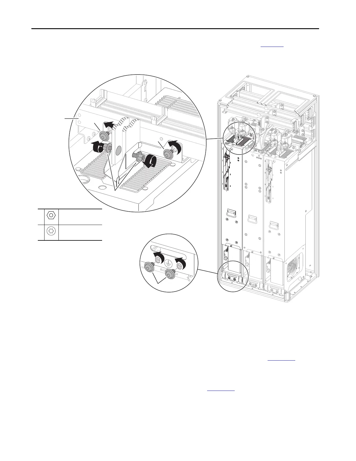
13. Remove the two M10 x 20 mm screws (see 2 in Figure 40) that secure
the power module chassis to the control bus frame.
Figure 40 - Chassis and DC Bus Connections
14. Leave the two M10 x 20 mm screws that secure the power module
chassis to the floor mounting bracket while preparing the PowerFlex
750-Series service cart or service ramp.
To remove the module using the PowerFlex 750-Series service cart,
follow the procedures detailed in the PowerFlex 750-Series Service Cart
and DCPC Module Lift Instructions, publication 750-IN105
.
To remove the module using PowerFlex 755TM service ramp, follow the
procedures detailed in the PowerFlex 755T Module Service Ramp
Instructions, publication 750-IN108
.
1
M10
15 mm Ratcheting Wrench
38 N•m (336 lb•in)
2
M10 x 20mm
T45
42.4 N•m (375 lb•in)
Leave these M10 screws in
place while preparing the
service cart or ramp.
Control bus frame.

 Loading...


