Publication 1747-UM011G-EN-P - June 2008
18 Quick Start for Experienced Users
2. Drill holes in the backpanel of your enclosure and install the top mounting hardware.
Use M4 or M5 (#10 or #12) phillips screw and star washer (or SEM screw).
3. Scrape off the paint from the backpanel between the chassis and backpanel.
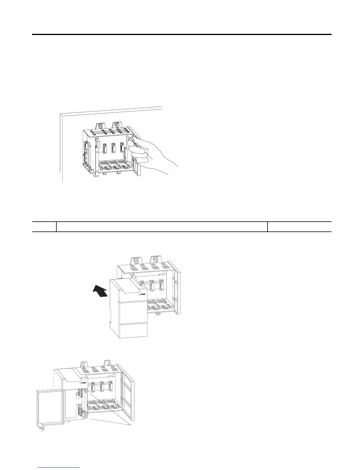
4. Slide the chassis over the installed hardware and tighten the screws.
5. Install the remaining tab hardware.
Chapter 6
(Installing Your
Hardware Components)
3. Install the power supply. Reference
1. Align the circuit board of the power supply with the card guides on the left side of the
chassis, and slide the power supply in until it is flush with the chassis.
2. Fasten the power supply to the chassis.
Chapter 6
(Installing Your
Hardware Components)
Use these screws to fasten the power supply to the chassis.
1.2 Nm (11 lb-in) Maximum Torque

 Loading...


