Publication 1747-UM011G-EN-P - June 2008
90 Identifying the Components of Your Processor
• multi-point list.
• UL listed to US and Canadian Safety Standards, CE compliant,
C-Tick marked.
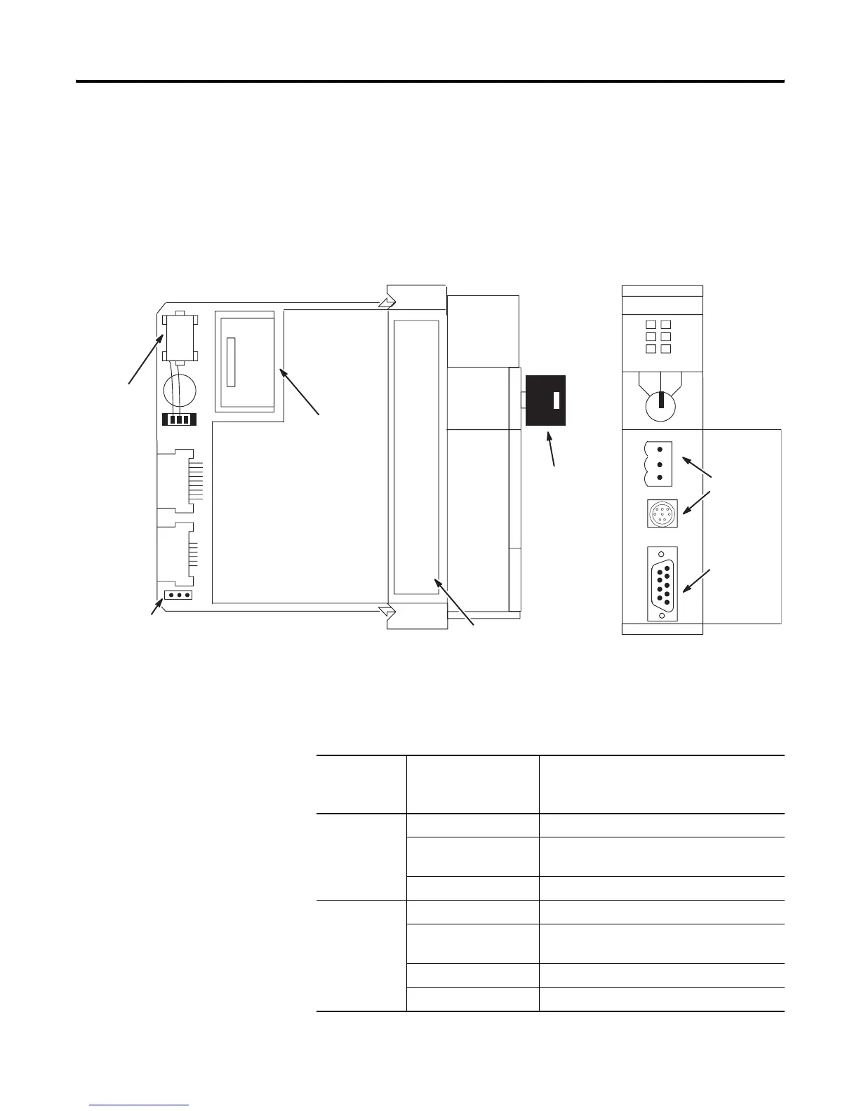
This figure below shows some of the hardware components of the
SLC 5/04 processors (1747-L541, 1747-L542, or 1747-L543).
SLC 5/04 Hardware Components
The table below provides a general explanation of each processor
status indicator on the SLC 5/04 processors.
SLC 5/04 Status Indicators
FORCE
DH+
RS232
RUN
FLT
BATT
RUN REM PROG
SLC 5/04 CPU
Memory
Module
Left Side View Front View
DH-485, DF1,
or ASCII
Channel 0
Battery
(provides
back-up
power for the
CMOS RAM)
Serial Number and
Catalog Number
DH+
Channel 1
Keyswitch
Operating System Download Protection Jumper
– do not move unless updating processor
Operating System firmware.
Processor
Status
Indicator
(1)(2)
When It Is Indicates that
RUN
(Color: green)
On (steady) The processor is in the Run mode.
Flashing (during
operation)
The processor is transferring a program from
RAM to the memory module.
Off The processor is in a mode other than Run.
FLT
(Color: red)
Flashing (at power up) The processor has not been configured.
Flashing (during
operation)
The processor detects a major error either in
the processor, chassis, or memory.
On (steady) A fatal error is present (no communication).
Off There are no errors.

 Loading...


