Layout and function
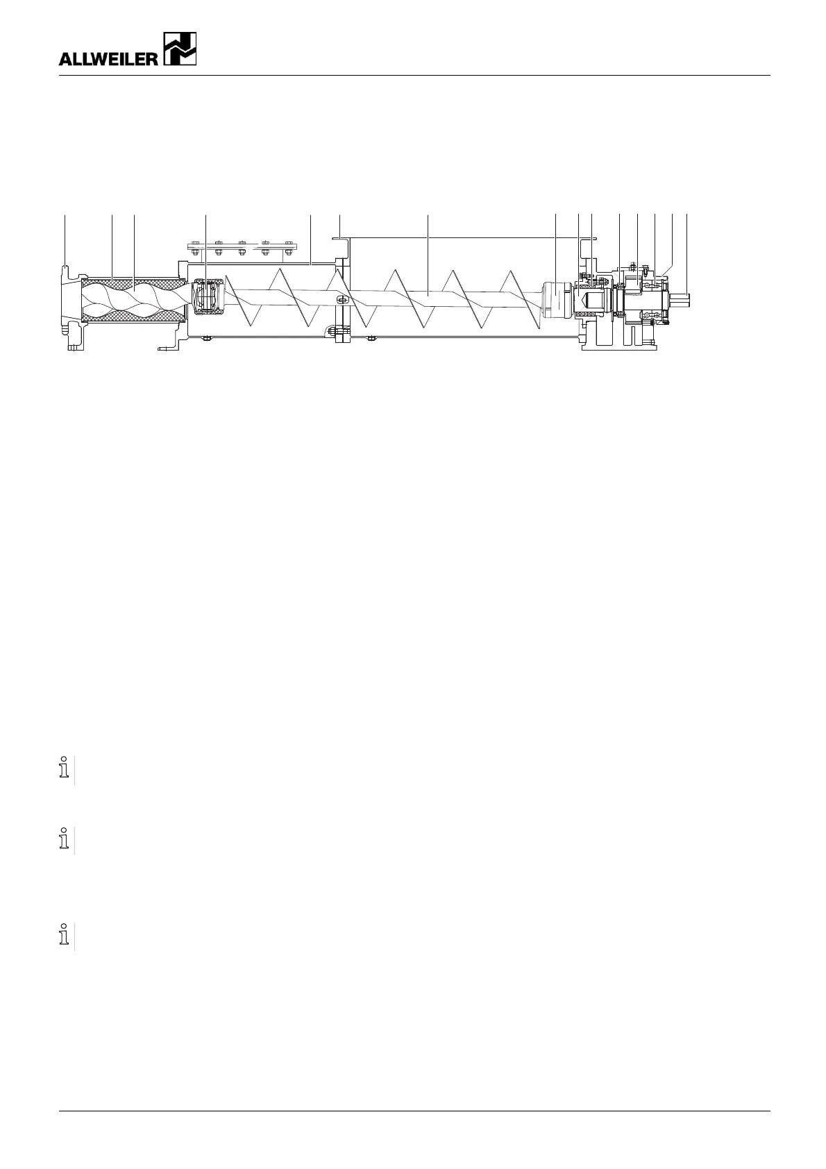
3.2.2 RG version (open-feed version with internal
gearbox mounting)
123 4 56
7489
10
11 10 12 13
Fig. 4 Layout – AE , RG design (ope n-feed version w ith internal gearbox mounting)
1 Pressure side 6
Suction side/suction casing
11
Spur gears
2
Stator
7
Universal joint shaft
12 Bearing pedestal
3 Rotor 8
Stub shaft
13
Top shaft
4 Joint 9
Shaft seal
5
Plug housing 10 Bearing
3.3 Function
• Self-priming, rotating po sitive displacement pump
• One, two, four or eight stages
• The rotor rotates in a station ary stator and displaces the
liquid in the direction of the pump outl et
• Transpo rt and dosage of, for example, highly viscous,
abrasive or solids-containing media
3.4 Shaft seals
Shaft seals used (→ Shaft seals, Page 44).
Only one of the followin g shaft seals can be used.
3.4.1 Packing gland
The packing gland must always leak slightly to carry the
frictional heat aw ay.
Packing gland, housing heated or co oled (optional).
3.4.2 Mechanical seals
Mechanical seals have fu nctional leaks.
• Single-action, unbal anced mechanical seal, optionally with
throttle ring
• Single-action mechanical seal with quenching
• Double-action, balanc ed mechanical seal with external
flushing
3.5 Bearings and lubrication
Close-coupled pump, IE, DE, ZE design:
• Bearing of the stub shaft in the reinforced beari ngs of the
drive motor
Directly mounted pump, ID, ZD, RG design:
• Angular and groove bal l bearings lubricated with grease
and protected from jet water
• Lubrication of the b earings via grease nipples (ID, ZD )
• Oil-lubricated spur gear (RG)
• Special designs possible on request, for example, oil bath
lubrication (ID)
Universal joint shaft:
• Oil-lubricated and liquid-en capsulated pin joints
260371 – 176-982/0 BA-2020.05 en-US AE 11