Setup and connection
5.7 Aligning the coupling precisely
Applies t o base plate versio n with c oupling
DANGER
Risk of death due to rotating parts!
Isolate the motor from its supply voltage and keep it locked
when carrying out any fitting o r maintenance work.
NOTE
Material damage due to incorrect alignment of the cou-
pling!
Align the motor exactly to the pump if there is any vertical,
lateral or angular misalignment.
For detailed information and spe c ial couplin gs: (→ manu-
facturer ’s specifications).
Checking the alignment of the coupling
Implements, tools and materials:
– Feeler gauge
– Straightedge
– Dial gau ge (for couplings with spacer piece)
– Other suitable tools, e.g. laser alignment instrument
1
2
A
Fig. 1 2 Checking the alignment of the coupling
1. Measure in two planes at an a ngle of 90° on the circumfer-
ence of the coupling.
2. Check the light gap towards the outer diameter with a
straightedge (1):
– Position the straightedge across both halves of the
coupling.
– Align the motor if there is a visible gap on the outer
diameter (→ 5.8 Aligning the motor, Page 21).
3. Measure the gap with a feeler gauge (2):
– Permissible gap (→ setup drawing)
– Use the feeler gauge to m easure the gap (A) between
the coupling halves.
– Align the motor if the gap is too wide (→ 5.8 Aligning
the motor, Page 21).
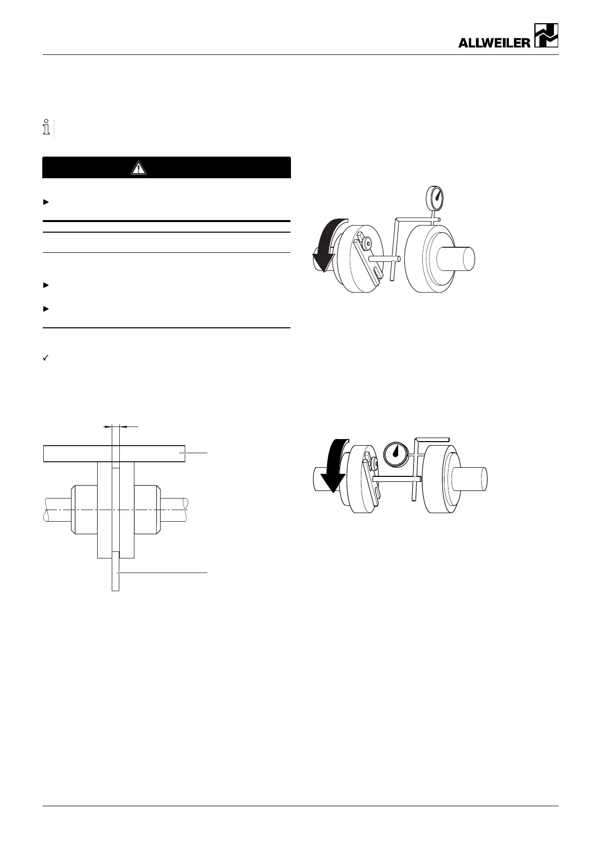
Fig. 13 Checking for lateral and vertical misalignment
4. Check for any lateral or vertical misalignment using the dial
gauge:
– Carry out the measurement as illustrated.
– Align the motor if there is any l ateral or vertical mis-
alignment (→ 5.8 Al igning the mo tor, Page 21).
Permissible axial or radial deviation, measured on the
coupling front or circumference, respectively: ±0.3 mm
Fig. 14 Checking for angular displacement
5. Check th e angular disp lacement with a dial gauge:
– Carry out the measurement as illustrated.
– If there is any angular displacement: align the motor.
20 AE BA-2020.05 en-US 260371 – 176-982/0