Setup and connection
5.2 Installation on a foundation
NOTE
Material damage due to distortion of the base plate!
Place the base plate on the foundation and secure it as
described in the following.
5.2.1 Placing the pump unit on the foundation
Implements, tools and materials:
– Foundation bolts (→ setup drawing)
– Steel washers
– Non-shrinking mortar grout
– Spirit level
1. Lifting the pump unit (→ 4.1 Transport, Page 13).
2. Attach the foundation bolts from below into the base plate
fixing ho les.
Observe the manufacturer’s instructions when using adhe-
sive anchors.
3. Set the pump unit down on the foundation. When doing
so, sink the foundation bolts into the prepared anchoring
holes.
32 1 2
Fig. 10 Installation with foundation
4. Use stee l washers to align the pump unit to the height and
system dimensions as described in the following:
– Placeasteelwasher(2)totheleftandright-handside
of each foundation bolt (1).
– If the distance betwe en the anchoring hol es is greater
than 750 mm, place ad ditio nal steel washers (3) in the
middle, on each side of the base plate.
5. Make sure the steel washers lie flat against the base plate,
in full co ntact.
6. Use the integrated spirit level to check whether th e pump is
level end to end and side to side with a maximum allowable
tilt of 1 mm/m.
7. Repeat the procedure until the base plate is correctly
aligned.
5.2.2 Fastenin g the pump unit
The dampin g behavior is improved by filling the base plate
with mortar grout. When filling, isolate any present adjust-
ing screw for the engine he ight adjustment.
1. Fill the ancho ring holes with mortar grout.
2. When the mortar grout has set, screw down the base plate
at th ree points with t he specified torque.
3. Before tightening the remaining bolts, compensate for any
unevenness in the surface using metal spacing shims next
to each bolt.
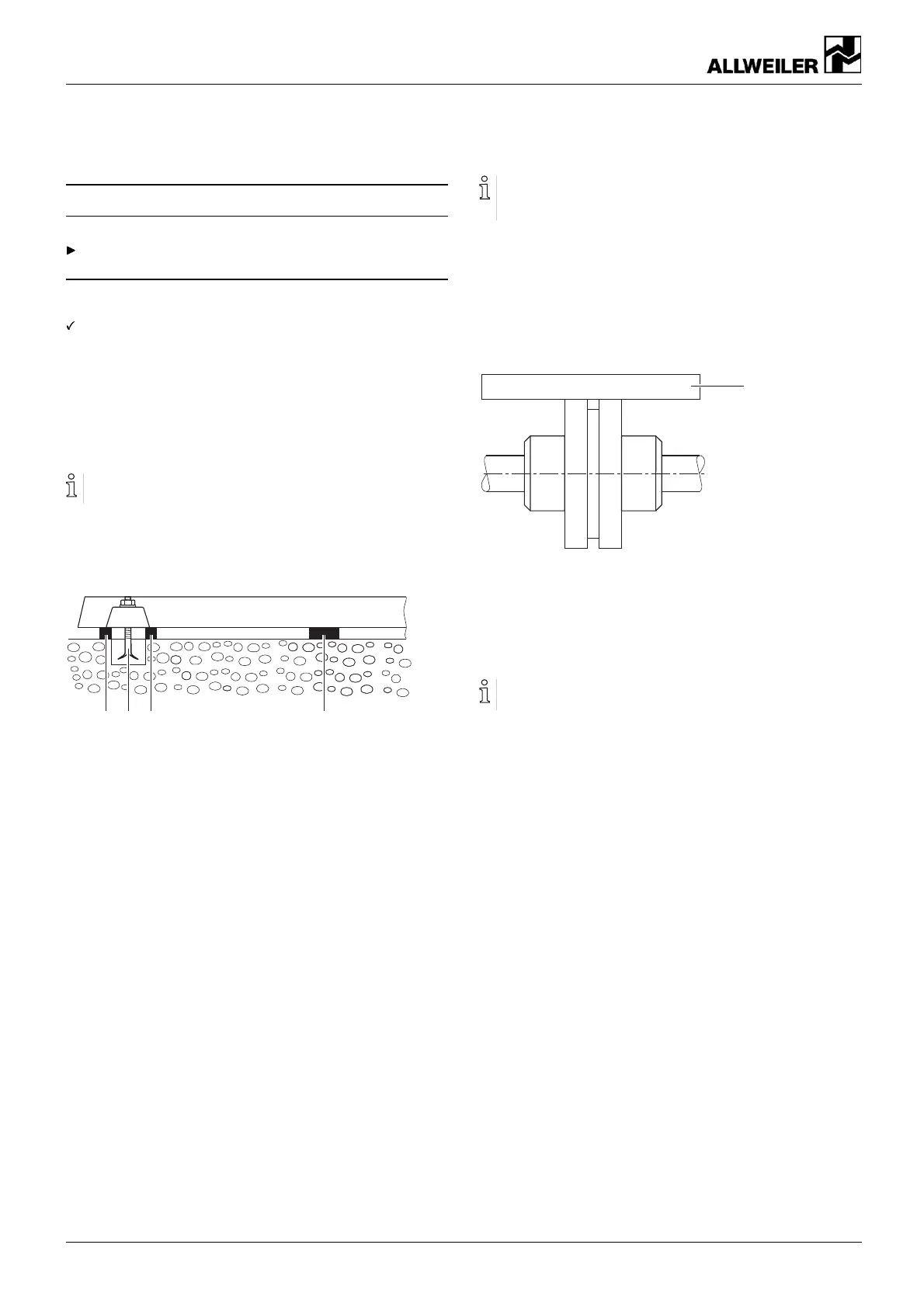
1
4. Check th e pump unit for any di stortion with a straightedge:
– Measure in two planes at an angle of 90° on the cir-
cumference of the coupling.
– Place the straightedge (1) over both coupling halves
and check the light gap at the outer diameter.
Couplings with s pacer piece (spacer coupling) can also be
checked with a dial gauge.
5. If there is signifi cant deviation, undo the fixing to the base
plate and correct the distortion by inserting more shims.
6. Fill the i nside of the base pl ate with concrete, if intended.
Knock on the base plate to ensure that no cavities are cre-
ated in the process.
16 AE BA-2020.05 en-US 260371 – 176-982/0