Overview
| 1-9
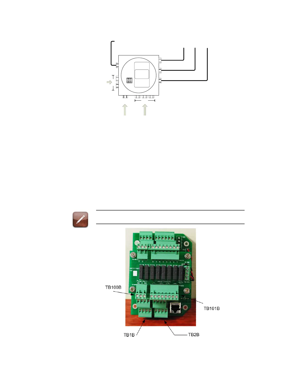
Customer Connection Enclosure
Figure 1-7a. Customer Connection Enclosure.
All customer power and signal connections are made within the customer
connection enclosure located below the electronics enclosure. Signal con-
nections are provided for Ethernet, Modbus, Alarm Relays, Analog Out-
puts, and Remote Inputs. The analyzer supports FTP and Telnet functions
over an Ethernet connection. The analyzer supports both ModbusRTU
and Modbus/TCP communication protocols. There are four relays: system
alarm, data valid, and two programmable relays. There are four congu-
rable (4-20 ma analog outputs). There is one remote input which can be
used to initiate one of the following options: Photo Span Calibration /
zero calibration /Steam Blowback.
See Appendix A for all model options wiring diagrams.

 Loading...


