Overview
| 1-7
Demister
The demister is used to condense sulfur vapor in the sample stream by lowering
the sample gas temperature to 129 °C. The demister cooling is done by injecting
air around the central demister tube that has been fitted with heat transfer fins.
Two coalescing pads (one Teflon® pad and one stainless steel pad) are located
inside the demister. The demister pads provide increased surface area to help
condense the sulfur vapor present in the stream. The air or nitrogen that is used
to cool the demister originates from SV1 (solenoid valve 1) on the solenoid valve
manifold in the electronics enclosure. The air or nitrogen enters the oven through
the tube bushing assembly. The demister temperature is measured by RTD 2.
Sample Cell
The sample cell module consists of either a 2.5” (6.35 cm) or 5” (12.7 cm) 316 stain-
less steel cell body, two UV-grade, fused silica windows, two Teflon® gaskets,
and two retaining rings. The fused silica windows are O-ring sealed at both ends.
The retaining rings and Teflon® gaskets hold the window against the O-rings.
The cell body has two ¼” Swagelok tube fittings to couple with the rest of the
sample system. The sample cell is secured to the light tube via 1 SST plate as well
as a thumb screw located below the center of the cell body.
Aspirator
The aspirator pressure regulator and pro-
portional solenoid valve (PSV) control the
flow of instrument air or nitrogen through
the aspirator. The air flow to the aspirator
enters through the tube bushing assembly
into the oven where the aspirator drive air
is pre-heated by an aluminum heat ex-
changer. There is also a check valve in series
with the aspirator drive air. The gas flow
produces a slight negative pressure in the
cell to move process gas through the sample
cell. The desired sample flow rate is 1.5 ±
0.5 liters-per-minute.
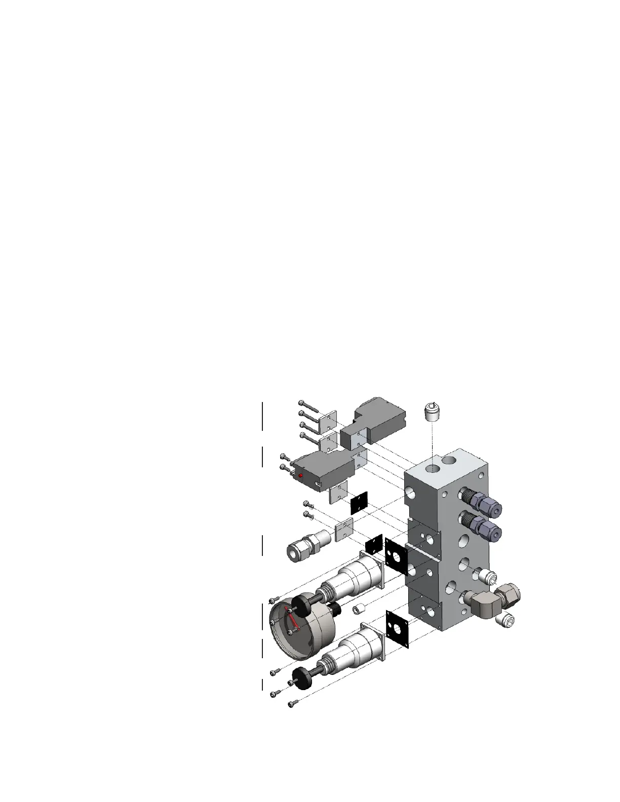
The manifold assembly is located in the
electronics enclosure. A part of that assem-
bly is a small gauge (Item 60, Figure 1-6).
Adjust the aspirator pressure regulator to
produce an output of approximately 10 PSI
above process pressure. The analyzer will
control the duty cycle to a PSV to keep the
sample flow rate at the desired level. Alter-
nately, the analyzer can be configured to
manually set the PSV duty cycle.

 Loading...


