Installation and Start Up
| 3-27
SV1 Dem-
ister
Normally
Closed
SV2-Flush Solenoid
Normally
Open
SV3-Steam
Blowback
Solenoid
Normally
Closed
FV3-Steam
Blowback Valve
Steam Blowback
Normally Closed
PV1-Aspirator
Proportional
Valve
Normally
Closed
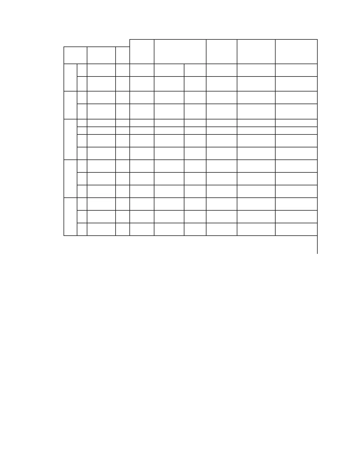
Period Name
Time
(s)
Zero
Calibration
1
Special
Flush
0 Controlling De-energized Open De-energized Closed Closed
2 Flush & Zero 60 Controlling De-energized Open De-energized Closed Closed
Sample
Cycle
3
Sample
Flush
60 Controlling Energized Closed De-energized Closed Open
4
Track
Sample
N/A Controlling Energized Closed De-energized Closed Open
Zero and Photo
Span Calibration
5 Flush & Zero 60 Controlling De-energized Open De-energized Closed Closed
6 Track Zero 0 Controlling De-energized Open De-energized Closed Closed
7
Photo Span
Calibration
60 Controlling De-energized Open De-energized Closed Closed
8
Track Photo
Calibration
10 Controlling De-energized Open De-energized Closed Closed
Steam Blowback
Cycle
9
Pre-Steam
Flush
10 Controlling De-energized Open De-energized Closed Closed
10
Steam Blow
Back
20 Controlling De-energized Open Energized Open Closed
11
Post Steam
Flush
60 Controlling De-energized Open De-energized Closed Closed
Special Periods
12
Continuous
Flush
N/A Controlling De-energized Open De-energized Closed Closed
13
Continuous
Hold
N/A Controlling Energized Closed De-energized Closed Closed
14
Continuous
Sample
N/A Controlling Energized Closed De-energized Closed Open
Logic Table-Fig. 3-9b (For Analyzer With Steam Blow Back.
Normal Timing Sequence
The Logic Table shows the sequential timing periods 1 through 14. When
power is first applied, the controller starts at Period 1 and cycles through
to Period 4, the Sample Tracking period. Sample tracking continues indefi-
nitely until one of the following events occurs:
1. When the Zero Timer times out, normally a Zero Cycle is started im-
mediately, but when the option is available, a Steam Blow Back Cycle
can also be started. When this timer times out, the Zero cycle begins at
Period 1, steps to Period 2 where the zero offset values are recorded,
steps to Period 3 and on to Period 4. This cycle, 1 → 2 → 3 → 4 → 1
and so on, constitutes the normal sampling operation loop.

 Loading...


