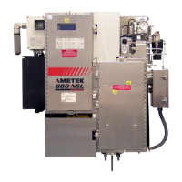
3-8 | Model 888 ATEX IECEx Tail Gas Analyzer
Installation Procedure
The sample gas contains highly toxic and corrosive substances. Proper
personal protective equipment including fresh air breathing appara-
tus, eye protection, and skin protection MUST BE worn when install-
ing the sample tap.
Refer to Figures 3-1 and 3-2 for locations of system components.
1. Locate and remove the bolts, nuts, washers, and lock washers from
the mounting hardware bag. Retain this hardware for use in Step 5.
2. The sample return valve (FV2), located at the bottom of the aspirator,
is a 3/8” valve which is closed when the handle is in a horizontal posi-
tion and open when in a vertical position.
Verify that this valve (FV2) is CLOSED (horizontal) before proceed-
ing. If it is left open, toxic gases from the tail gas line can flow back
through the sample system while the probe is being installed.
3. Verify that the main sample valve on the tail gas pipe is closed. At this
point, ALL PERSONNEL IN THE IMMEDIATE AREA MUST USE
FRESH-AIR BREATHING APPARATUS.
4. Remove the blind flange from the ball valve. Test to make sure that the
valve is not leaking toxic process gases. If toxic gases are not detected
in the area, it is safe to remove the fresh-air apparatus until the probe
installation (Step 8).
5. Install a gasket on the top of the steamjacketed main sample valve. Us-
ing suitable lifting equipment, lower the analyzer into place so that:
- The analyzer back plate is parallel with the tail gas pipe, and
- The sample inlet flange and main sample valve flange bolt patterns
line up. Use the nuts, washers, and lockwashers (set aside in Step 1)
to bolt the flanges together. Use a calibrated torque wrench to torque
the bolts in a cross pattern to 54.25 N-m (40 ft.-lbs).
The integrity of the connection between the analyzer sample inlet
flange to the tail gas pipe flange is critical as it provides the primary
support for the analyzer.
!
WARNING
!
!
CAUTION

 Loading...


