Overview
| 1-3
In this analyzer, the photometer spans from the electronics enclosure
to sample conditioning enclosure. The electronics enclosure houses the
source and detector assemblies. The sample conditioning enclosure
houses the light tube, mirror-block, and sample cell assemblies. All of the
photometer components are rigidly connected for optical stability.
Xenon Lamp Assembly
The source module consists of a high quality 3 mm arc xenon flash lamp,
0.1 uF close-coupled capacitor, and trigger electronics (with 50 Hz flash
rate). The close-coupled capacitor and trigger electronics are potted inside
a metal enclosure. The xenon lamp assembly is powered from the Xenon
Lamp Power Supply PCB.
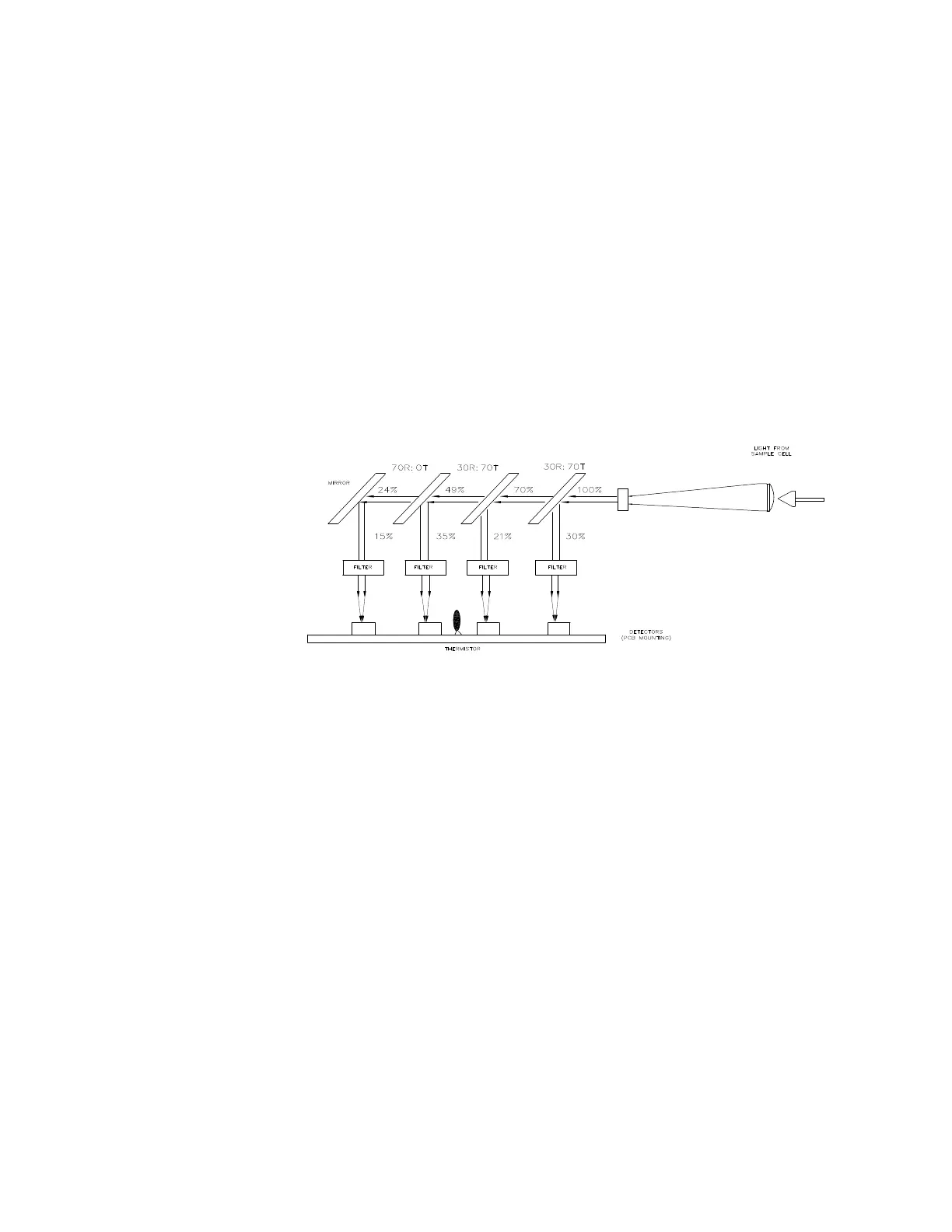
Detector Assembly
Figure 1-3. Detector
The detector assembly consists of focusing optics, three beam splitters,
one front surface mirror, four band pass filters for wavelength selection
(centered at 232, 254, 280, and 400 nm), four silicon photodiodes, and
electronics. Upon exiting the sample cell, the light re-enters the electronics
and is optically conditioned into the detector assembly. The beam splitters
and mirror divides passing light through the four band pass filters (wave-
length selection) before reaching the photodiodes. The band pass filters
are temperature controlled for improved performance. The photodiodes
are soldered to the Detector PCB. The Detector PCB performs the signal
acquisition and integration. The signal information is then sent to the Sen-
sor PCB.

 Loading...


