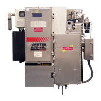
3-18 | Model 888 ATEX IECEx Tail Gas Analyzer
- This disconnect device must be in close proximity to the equipment
and in easy reach of an operator.
- The device must be permanently marked as the disconnect device
for this equipment.
3. Signal I/O connections are also made in the same enclosure mounted
below the electronics enclosure. Refer to Figure 3-4 for details. All
customer wiring must have a minimum working voltage of 300VRMS.
Refer to the Specifications section (Chapter 2) for customer signal
input voltage and current restrictions. A separate junction box may
be required if the signal cables are too large in diameter to fit the M25
entry holes.
System Start-Up and Operation
Leak Checking
Before power is applied and before the sample inlet valve is opened to the
process gas stream, it is necessary to ensure that no leaks are present in
the sample system.
It is recommended that the sample system be leak checked after any
maintenance or modifications.
Leak Checking (without power)
Necessary equipment: Pressure gauge, shut-off valve, and a regulated air
supply. Arrange the components as indicated below.
Regulated
Air Supply
→
Shut-Off
Valve
→
Pressure
Gauge
→
Utility
Port of Analyzer
Procedure
• Close both the sample inlet and return valves on the analyzer.
• Supply 50 psig to the utility gas inlet and lock it in using the shut-off
valve.
• Monitor the pressure gauge for any drops in pressure.
!
CAUTION

 Loading...


