Installation and Start Up
| 3-17
AWG), and separate earth/protective ground (PE) (14 AWG). The Ana-
lyzer must be externally connected to an M5 stud via an 11 AWG wire
located to the right side of the customer connections enclosure. Refer
to Figure 3-5 for connection details. DO NOT CONNECT SPLIT-
PHASE POWER TO THIS ANALYZER. Six (6) M25 holes are provided
for power and signal cable gland entry/installation. If the incoming
power cable is too large, a separate junction box must be provided that
can accept the main cable and suitable jumpers used from this box
to the analyzer’s junction box. Ensure that all unused M25 holes are
plugged with hardware appropriate to the area classification.
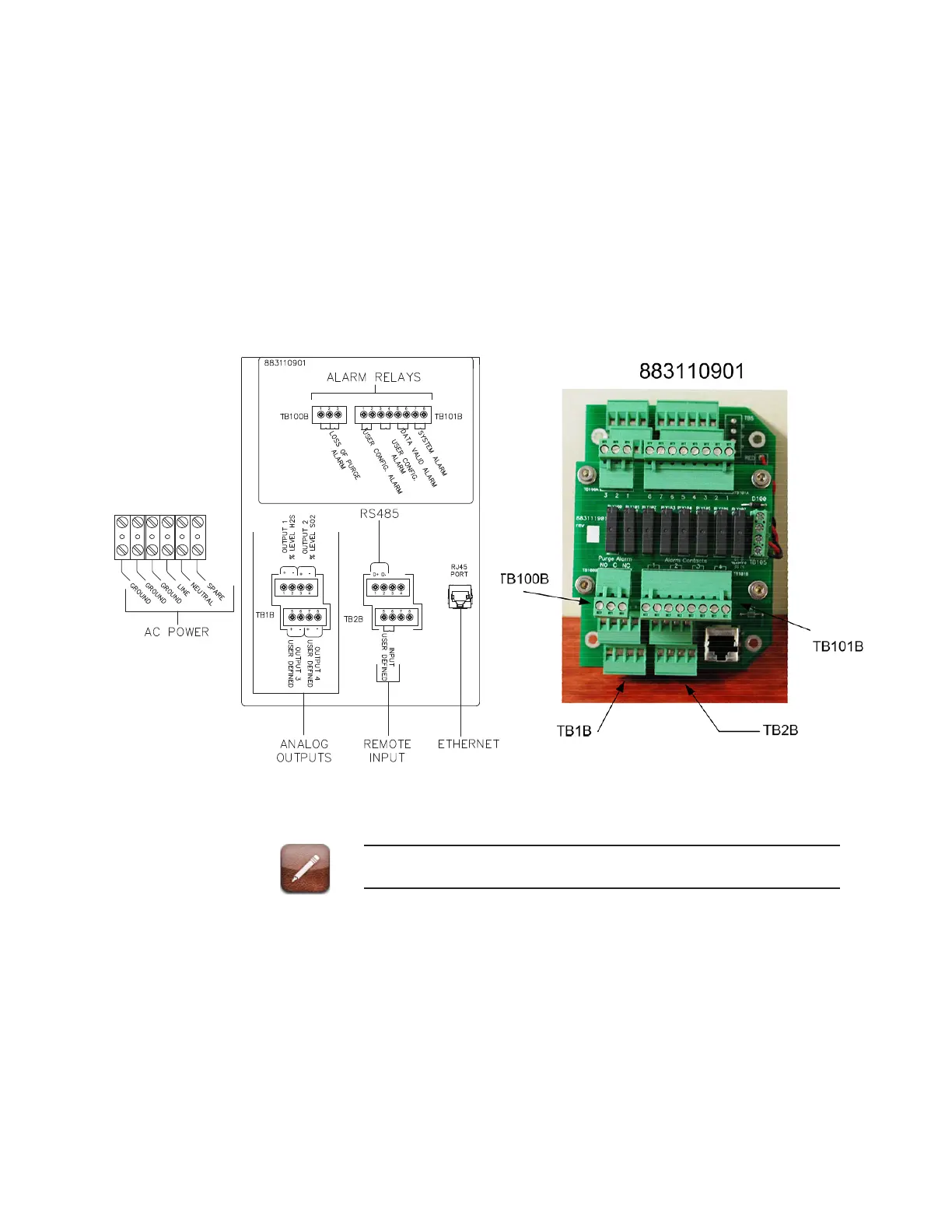
Figure 3-5b. Interconnect Wiring Diagram.
Refer to Appendix A for wiring diagrams for all model options.
As a permanently connected piece of equipment without an accessible
power switch, the installation must have the following characteristics:
- The installation must include an external disconnect device, such as
a switch or circuit breaker, included as part of the installation. The
electrical specifications of this device must accommodate the power
and environmental requirements of the equipment for the particular
application.

 Loading...


