3-32 | Model 931S / Model 932S UV Analyzers
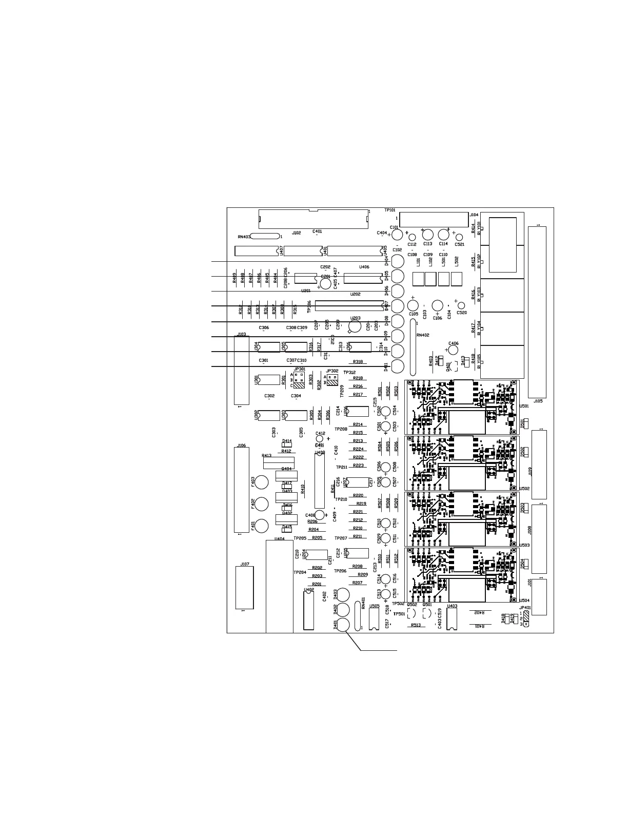
b. Upon power-up, all solenoids will remain de-energized (off)
for at least five minutes. Verify this by viewing the red LEDs
D409 (Span1 Solenoid), D410 (Span2 Solenoid), and D411 (Zero
Solenoid) on the Customer I/O board. These LEDs should be OFF.
(This may vary, depending on system configurations.)
c. The Probe heater (if the Heated Sample Probe is used) will be
turned on to heat up the Probe. Verify this by viewing the red
LED D401 on the Customer I/O board. It should be ON steady or
pulsing.
Figure 3-11.
Customer I/O board
(P/N 100-1758).
LED D404 (Fault Relay)
LED D405 (Warning Relay)
LED D406 (Alarm Valid)
LED D407 (Concentration Alarm1)
LED D408 (Concentration Alarm2)
LED D409 (Span1 Solenoid)
LED D410 (Span2 Solenoid)
LED D411 (Zero Solenoid)
D401 (Probe Heater)
 Loading...