4-46 | Model 931S / Model 932S UV Analyzers
Modbus Settings
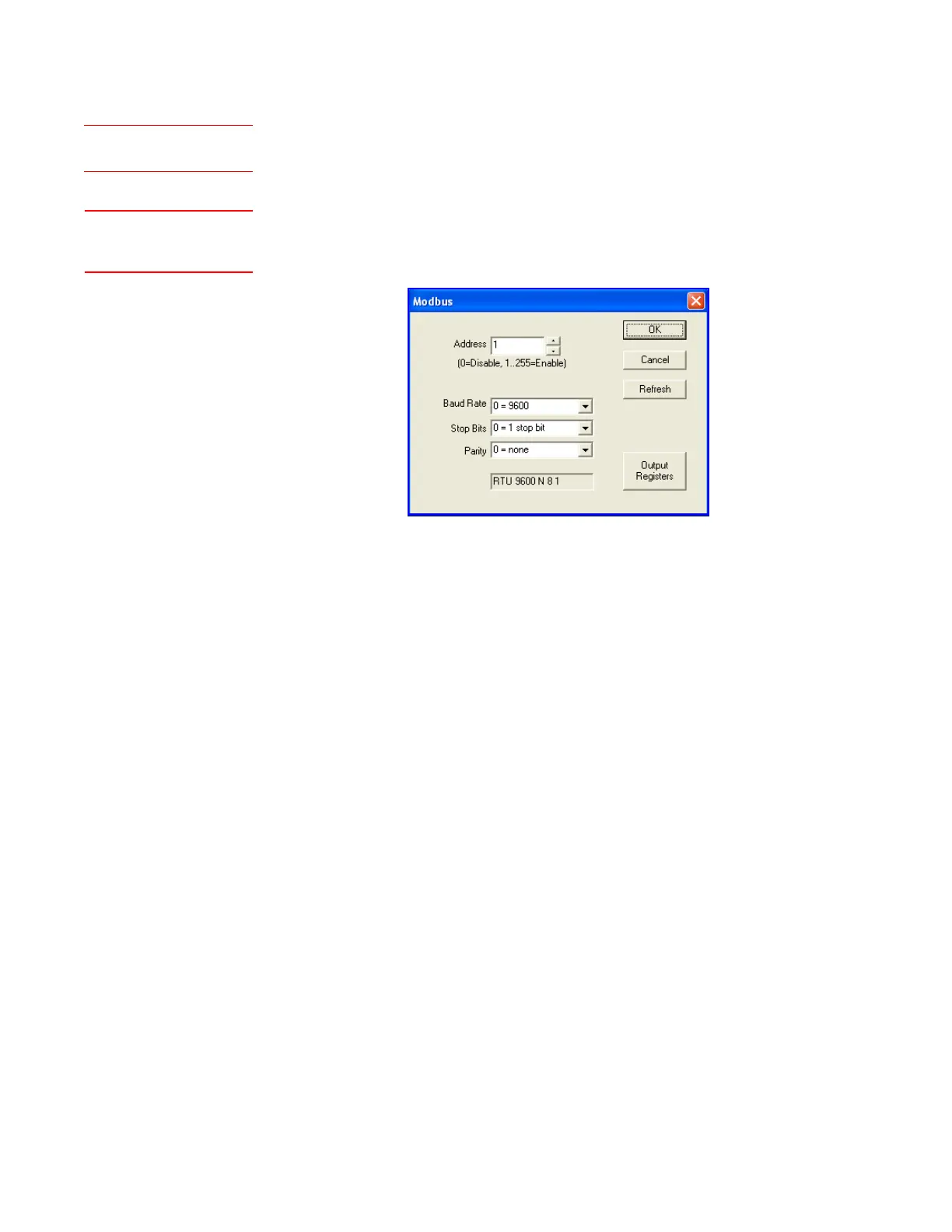
The Modbus dialog box displays current communication parameters for
the analyzer you are communicating with. The parameters displayed here
are the results of settings in the analyzer.
Certain parameters need to be set up using the Configurator Software
to enable the Modbus port to establish communication with the Modbus
master.
Set up the following information:
Address
Enter the Modbus network address assigned to the analyzer.
Baud Rate
Select the baud rate of the Modbus network.
Stop Bits
Select the number of stop bits of the Modbus network.
Parity
Select the parity of the Modbus network.
Output Registers button
Allows you to create a CSV (comma separated value) text file of all
of the Modbus Registers associated with the analyzer, and the value
(setting) for each register. The suggested filename will be predeter-
mined based on coded information from that analyzer (example,
m932-YY-932S-JJJJ-N). This file can then be imported and opened us-
ing MS Excel.
The field at the bottom of this dialog box (that is, RTU 9600 N 8 1 in Figure
4-15) represents the current settings.
Figure 4-15.
Modbus dialog box.
Setup (tab)Modbus
See also “Digital
Communication” in Chapter 3.
 Loading...


