Controller / User Interface | 4-23
‘**’ following the parameter names below indicates the parameter
should only be modified by a trained technician.
Lamp Base (mV)**
The minimum operating current control setpoint for each source
lamp.
1 = Lamp 1 (closest to the Measuring Cell)
2 = Lamp 2 (farthest from the Measuring Cell)
Default Filter Pulses (mV)
The source lamp pulse current control signal for each filter. The
normal operating range is between the Lamp Base and Lamp Max
settings; the control signal for the key filter is Lamp Max. If a filter
position is not used, the Default Filter Pulse value must be set to a
negative number. The recommended value is negative base (-2000 mV)
setpoint.
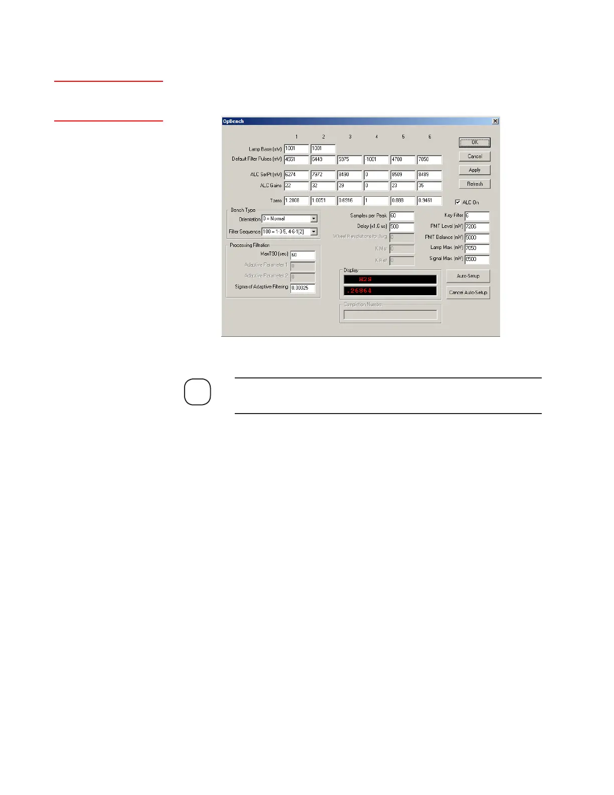
Optical Bench
The Optical Bench dialog box allows Optical Bench control and data ac-
quisition parameters to be viewed and modified.
NOTE
Setup (tab)Optical
Bench
Figure 4-10.
Optical Bench dialog
box (Model 932S).
 Loading...


