Page 25
EWCIE Technical Manual
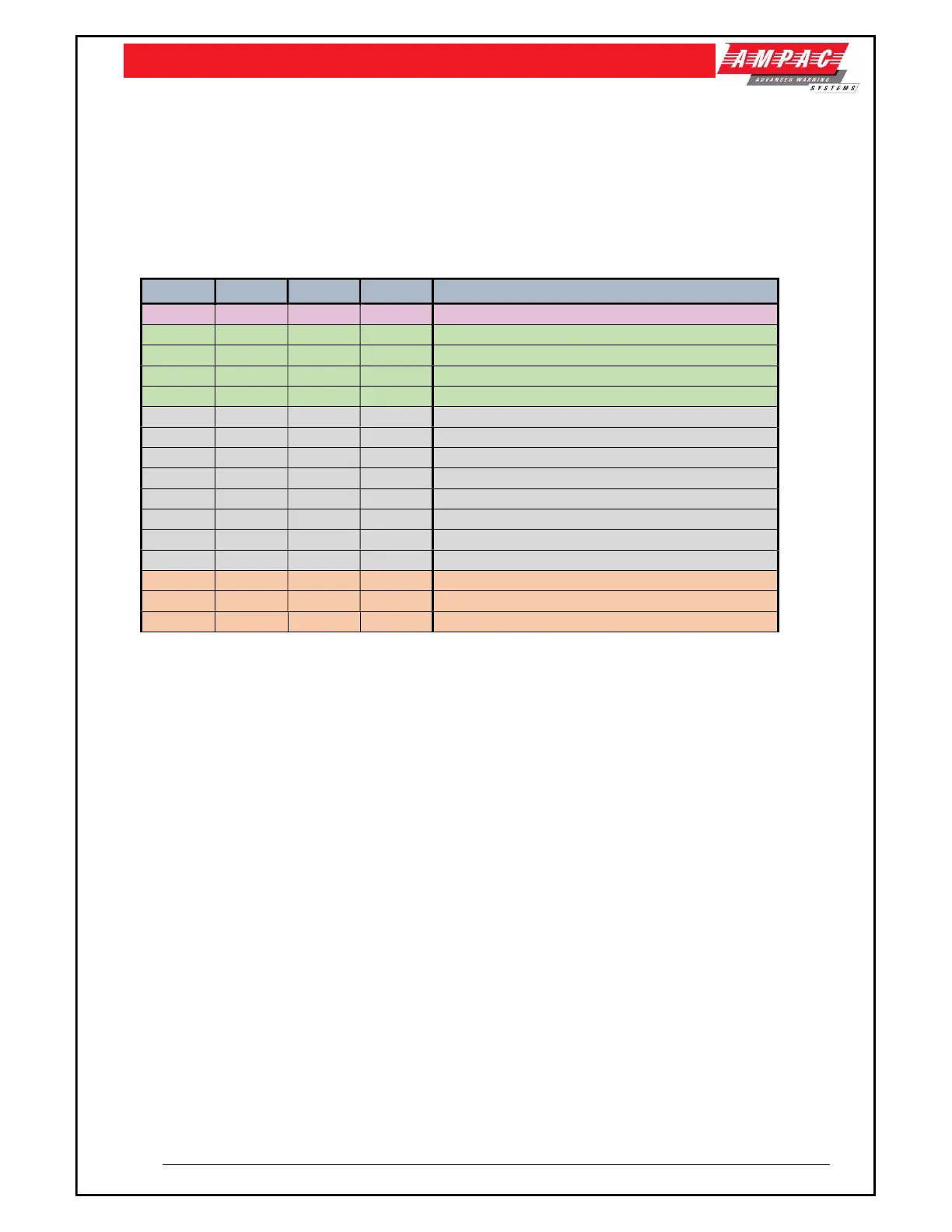
8.5 DIP switch settings
Address DIP switch settings.
Note: Addresses 1-4 to be used only with CAN bus monitoring.
Addresses 5 to 12 are not used.
Addresses 0, 13, 14 and 15 are used when the ASL’s inputs and fault output are hardwired (This
option is when there are 3 to 6 ASL’s required).
The table below shows the applicable settings.
Switch 1 Switch 2 Switch 3 Switch 4 Description
OFF OFF OFF OFF No CAN bus - Normal
ON OFF OFF OFF CAN bus Address 1
OFF ON OFF OFF CAN bus Address 2
ON ON OFF OFF CAN bus Address 3
OFF OFF ON OFF CAN bus Address 4
ON OFF ON OFF Address 5 – Not used
OFF ON ON OFF Address 6 - Not used
ON ON ON OFF Address 7 – Not used
OFF OFF OFF ON Address 8 – Not Used
ON OFF OFF ON Address 9 – Not Used
OFF ON OFF ON Address 10 – Not Used
ON OFF OFF ON Address 11 – Not Used
OFF OFF ON ON Address 12 – Not Used
ON OFF ON ON No CAN bus – Inverted Inputs
OFF ON ON ON No CAN bus – Inverted fault, Inverted Inputs
ON ON ON ON No CAN bus – Inverted Fault