Page 32
EWCIE Technical Manual
10.4.2 5 Amp PSU
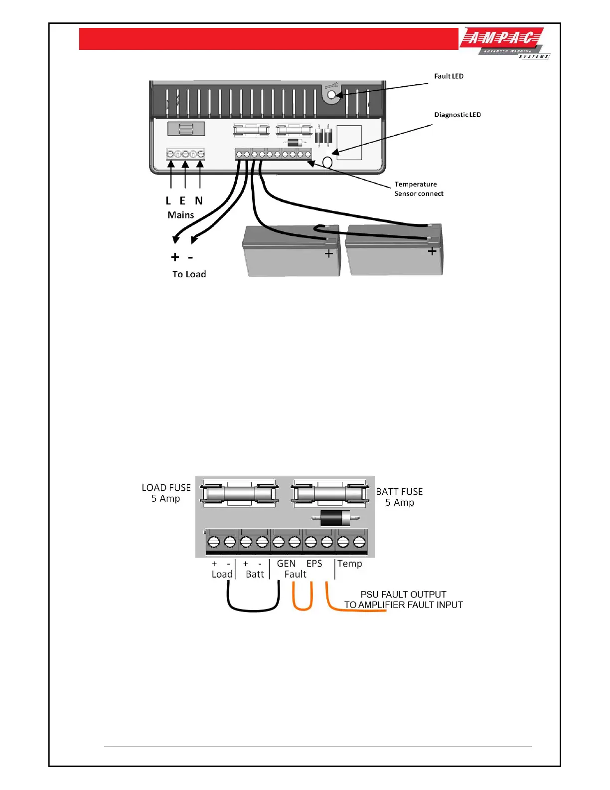
Figure 14: 5 Amp PSU shown
With mains disconnected, connect the two 12 V standby batteries in series using the single
cable provided. Connect the negative of one battery to the positive of the other. DO NOT
CONNECT the other two battery terminals to each other.
Connect the free Positive and Negative terminals of the batteries to the PCB terminals Batt+
and Batt - using the cables provided.
Apply mains and, after the LED indicators initial start-up flash, verify that the yellow Fault LED
does not flash (battery connection detected).
Disconnect the mains power. Verify that the green Mains LED extinguishes and the yellows
Fault LED starts to pulse (indicating that the PSU is running from its standby batteries).
Verify that the EWCIE Front Control indicates a fault.
Reconnect the mains. Verify that the green Mains LED illuminates and the yellow Fault LED
extinguishes
Figure 15: 5 Amp PSU Terminals shown
Note: For the EWCIE to monitor PSU faults the PSU’s GEN and EPS fault relays must be
wired as per the image above and connected to an amplifiers External Fault Input 4.
Note: For further 5A PSU specifications refer to MAN3086