Page 3
EWCIE Technical Manual
1 About This Manual
1.1 Introduction
This manual contains all the information required to install, program and operate the AMPAC EvacU
range of Emergency Warning Control and Indicating Equipment (EWCIE), formally referred to as
Occupant Warning System.
1.2 References
AS 4428.16:2015 Emergency Warning Control and Indicating Equipment
1.3 Symbols
Important operational information
Note: Configuration considerations
Observe antistatic precautions
2 System Overview
Designed to comply with the requirements of AS 4428.16:2015 EWCIE Grades 2 and 3 the EvacU
EWCIE is intended to broadcast information (voice announcements for emergency purposes, alert
signals, evacuate signals, visual and tactile warning devices) to provide warning to the occupants within
one or more specified areas in an emergency, to effect a rapid and orderly mobilisation of occupants in
an indoor or outdoor area.
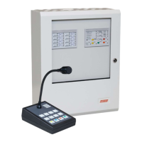
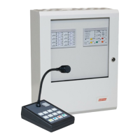
Whether combined in Ampac’s Fire Control Panels (FACP) or as a fully self-contained Standalone
System the EWCIE consists of the Amplifier/s, a Front Panel Switch and Indicator Module and optional
Zone Indicating Module, Line Monitoring Units and Remote Paging Console (RPC).
When combined in the FACP the EWCIE communicates with the Fire panel range by either RS485
communication (FireFinder Plus, LoopSense) or by hardwired inputs (ZoneSense Plus, FireFinder).
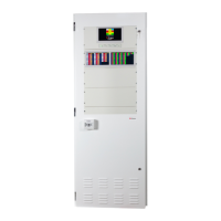
Alternatively, when the EWCIE is in the Standalone Cabinet or installed with Non-Ampac Fire panels
the communication is by hardwired inputs only.
The Amplifier, Front control, Zone Indicator, Line Monitor and RPC communicate with each other via a
CAN bus.
Up to 8 Amplifiers can be daisy chained via the CAN bus. Each amplifier supports:
100VAC speaker circuit (which supports up to 3 branches)
Strobe output
4 digital inputs
3 relay outputs
RPC/BGM interface
The Front Control Switch and Indicator Module is an “ALL CALL” card and will control all amplifiers.
When individual Emergency Zone speech is required the Zone Indicator Module is required and the
Amplifiers must be associated to an Emergency Zones from 1-8 using the EvacUwiz programming tool.
The Line Monitoring Unit allows a single amplifier 100V line to be split into 4 Paging Zones. Up to to 8
Paging zones can be programmed using the EvacUwiz programming tool.
Emergency Zones and Paging Zones are not necessarily the same zone.