Page 7
EWCIE Technical Manual
4 Front Panel Switch and Indicator Module
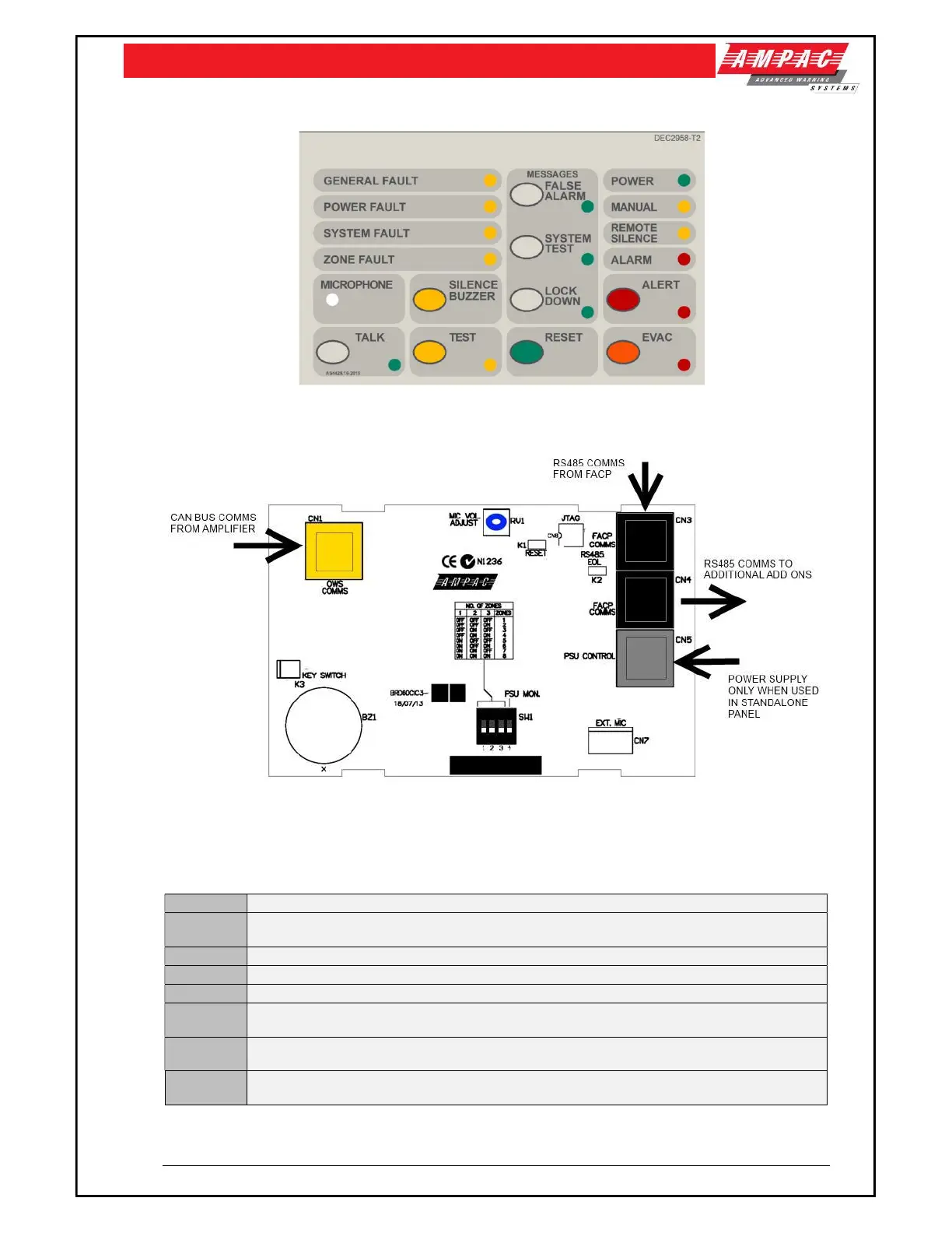
Figure 2: Front Panel Switch and Indicator Module
Figure 3: Front Panel Switch and Indicator Card PCB
4.1 Connectors
CN1 CAN BUS communication between the Front Panel Switch and Indicator Card and the Amplifiers
CN3, CN4
RS485 Add On communications when connecting the EWCIE to FireFinder Plus and LoopSense
FACP’s
CN5 External Power Supply Monitoring. Required in the standalone version.
CN7 Optional External hand held Emergency Microphone connection.
K1 Not Fitted
K2
RS485 EOL Link. Only fitted if the Front panel Switch and Indicator Card is the last Add-On
Module fitted in the FACP.
K3
Controls Enable. Default – fitted with a jumper link (controls always enabled). Can be connected
to a key switch, for controls to be key activated.
RV1
Used to adjust the microphone signal level so the sound is loud, clear and distortion free.
Adjustment should be done before commissioning time.