Page 33
EWCIE Technical Manual
10.4.3 10 Amp PSU
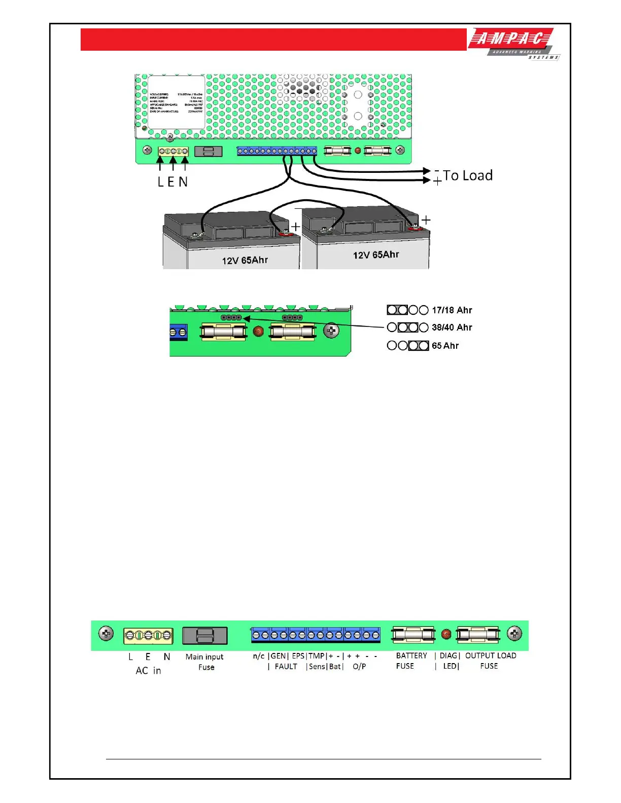
Figure 16: 10 Amp PSU shown
Figure 17: 10 Amp PSU Battery Selection Links
Select the Battery type by placing the link (above the Battery fuse) in the appropriate location
to select (17/18 Ah, 38/40 Ah or 65 Ah) batteries. This changes the maximum bulk charge
current, and therefore enables higher load current to be used when smaller batteries are
required. Put the link on the left hand two pins for 17/18 Ah, the middle pins for 38/40 Ah and
the right hand two pins for 65 Ah batteries
With mains disconnected, connect the two 12 V standby batteries in series using the single
cable provided. Connect the negative of one battery to the positive of the other. DO NOT
CONNECT the other two battery terminals to each other.
Connect the free Positive and Negative terminals of the batteries to the PCB terminals Batt+
and Batt - using the cables provided.
Apply mains and, after the LED indicators initial start-up flash, verify that the yellow Fault LED
does not flash (battery connection detected).
Disconnect the mains power. Verify that the green Mains LED extinguishes and the yellows
Fault LED starts to pulse (indicating that the PSU is running from its standby batteries).
Verify that the EWCIE Front Control indicates a fault.
Reconnect the mains. Verify that the green Mains LED illuminates and the yellow Fault LED
extinguishes
Figure 18: 10 Amp PSU Terminals shown
Note: For further 10A PSU specifications refer to MAN3087