16 I
I – 2 Milling Specific Operations
Incline Milling
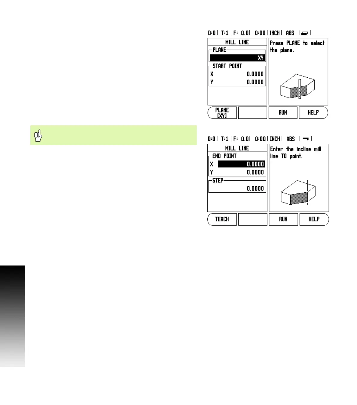
Entry Form: (See Fig. I.21 Entry Form: Start Point) and (Fig. I.22 Entry
Form: End Point)
The Incline Milling form is used to specify the flat surface to be milled.
Press the INCLINE MILLING hard key to open the form
Plane - Select the plane by pressing the PLANE soft key. The current
selection is shown on the soft key and in the plane field. The graphic
in the message box aids in selecting the correct plane.
Start Point: Enter the coordinates of the start point or press TEACH
to set the coordinate to the current position.
End Point: Enter the coordinates of the end point or press TEACH
to set the coordinate to current position.
Step: Enter the step size. When milling, this is the distance
between each pass or each step along the line.
Press ENTER or RUN to execute the surface milling operation. Press C
to exit the form without executing. Settings are retained until power
is turned off.
Execution
Execute the milling operation by opening the entry form and
pressing the RUN soft key or ENTER key. The screen switches to the
incremental DRO view.
Initially, the DRO shows the current incremental moving distance
from the start point. Move to the start point and make a plunge cut
or the first pass across the surface. Press the NEXT PASS soft key to
continue with the next step along the contour.
After pressing NEXT PASS, the incremental display shows the
distance from the next step along the line’s contour.
If no step size was specified, the incremental display always shows
the distance from the closest point on the line. To follow the
contour, move the two axes in small steps, keeping the (X, Y)
positions as close to 0 as possible.
Fig. I.21 Entry Form: Start Point
Fig. I.22 Entry Form: End Point
The Step size is optional. If the value is zero, the operator
decides at run-time how far to move between each step.