22 I
I – 3 Turning Specific Operations
Datum Setting
See "Datum Setting" on page 8 for basic information. Datum settings
define the relationships between the axis positions and the display
values. For most lathe operations there is only one X-axis datum, the
center of the chuck, but it may be helpful to define additional datums
for the Z-axis. The table can hold up to 10 datum points. The easiest
way to set datum points is to touch a workpiece at a known diameter
or location, then enter that dimension as the value that the display
should be showing
...
Example: Setting a workpiece datum. See Fig. I.30.
Preparation:
Call the tool data by selecting the tool which you are using to touch the
workpiece. Press the DATUM hard key. The cursor will be in the DATUM
NUMBER field. Enter the datum number and press the DOWN ARROW key
to go to the X-axis field. Touch the workpiece at point 1. Enter the
radius or diameter of the workpiece at that point.
Remember to ensure the Wizard 411 is in diameter display mode (Ø)
if you input a diameter value. Press the DOWN ARROW key to advance to
the Z axis.
Touch the workpiece surface at point 2. Enter the position of the tool
tip (Z= 0) for the Z coordinate of the datum. Press ENTER.
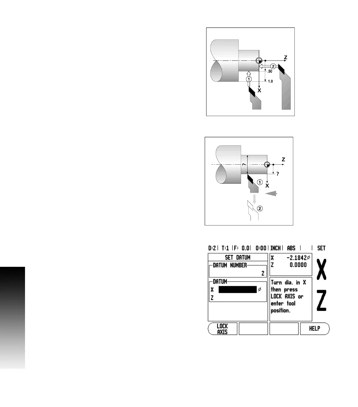
Setting Datums using LOCK AXIS Function
The LOCK AXIS function is useful for setting a datum when a tool is
under load and the diameter of the workpiece is not known. See Fig
Fig. I.31.
To use the LOCK AXIS function:
Press the DATUM hard key. The cursor will be in the DATUM NUMBER
field. Enter the datum number and press the DOWN ARROW key to go to
the X axis field. Turn a diameter in the X axis. Press the LOCK AXIS soft
key while the tool is still cutting. Retract from the current position.
Turn the spindle off and measure the workpiece diameter. Enter the
measured diameter, for example, 1.5” and press ENTER.
Fig. I.30 Setting a workpiece datum
Fig. I.31
Fig. I.32 Setting Datum using LOCK AXIS