Wizard 411 27
II – 1 Installation Setup
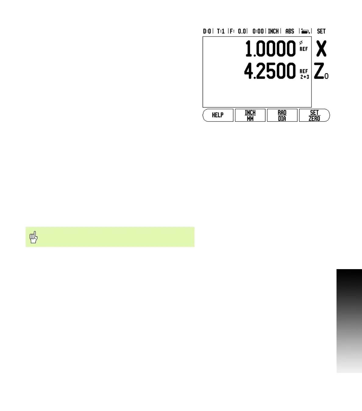
Enabling Z Coupling
To couple the Z
0
and Z axis and have the result displayed on the Z
0
display, press and hold the Z
0
key approximately 2 seconds. The sum
of the Z positions will be displayed on the Z
0
display and the Z display
will be blanked. See Fig. II.4.
To couple the Z
0
and Z axis and have the result displayed on the Z
display, press and hold the Z key for approximately 2 seconds. The
sum of the Z positions will be displayed on the Z display and the Z
0
display will be blanked. The coupling is preserved in between power
cycles.
Moving either Z
0
or Z inputs will update the coupled Z position.
When a position is coupled, the reference mark for both encoders
must be found in order to recall the previous datum.
Disabling Z Coupling
To disable Z Coupling, press the axis key of the display that is blank.
The individual Z
0
and Z display positions will be restored.
Error Compensation
The distance a cutting tool travels, measured by an encoder, can in
certain cases, differ from the actual tool travel. This error can occur
due to ball screw pitch error or deflection and tilting of axes. This error
can either be linear or non-linear. You can determine these errors with
a reference measurement system, ex. gauge blocks, laser, etc. From
an analysis of the error it can be determined which form of
compensation is required, linear or non-linear error.
The Wizard 411 provides the opportunity to compensate for these
errors and each axis can be programmed separately with the
appropriate compensation.
Fig. II.4 Enabling Z Coupling
Error compensation is only available when using linear
encoders.