Wizard 411 25
II – 1 Installation Setup
II – 1 Installation Setup
Installation Setup Parameters
Installation setup is accessed by pressing the SETUP soft key, which
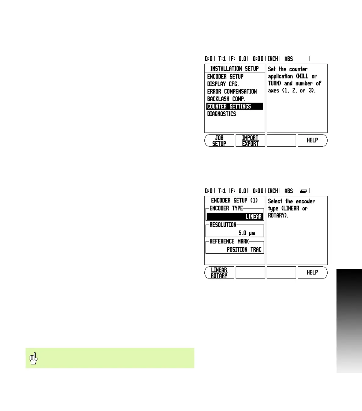
brings up INSTALLATION SETUP soft key. See Fig. II.1.
Installation Setup parameters are established during the initial
installation and, most likely, will not often change. For this reason, the
installation setup parameters are protected by the passcode.
See "Readout Parameter Access Code" on page iii
Encoder Setup
The ENCODER SETUP is used to set the encoder resolution and type
(linear, rotary), count direction, reference mark type. See Fig. II.2.
8 The cursor will default to the ENCODER SETUP field upon opening
Installation Setup. Press ENTER. This opens a list of possible encoder
inputs.
8 Scroll to the encoder you want to change and press ENTER.
8 Cursor will be in the ENCODER TYPE field, select the encoder type
by pressing the LINEAR/ROTARY soft key.
8 For linear encoders, cursor to the RESOLUTION field and use
COARSER or FINER soft keys to select the encoder’s resolution in µm
(10, 5, 2, 1, 0.5) or type in the exact resolution. For rotary encoders,
enter the number of counts per revolution.
8 In the REFERENCE MARK field, toggling the REF MARK soft key
selects whether the encoder has no reference signal with NONE,
single reference mark with the SINGLE or with the P-TRAC soft key
for encoders with the Position-Trac™ feature.
8 In the COUNT DIRECTION field, select the count direction by
pressing the POSITIVE or NEGATIVE soft key. If the encoder’s count
direction matches the user’s count direction, select positive. If the
directions do not match, select negative.
8 In the ERROR MONITOR field, select whether the system will
monitor and display encoder errors by selecting ON or OFF. When an
error message occurs, press the C key to remove it.
Fig. II.1 Installation screen
Fig. II.2 Encoder Setup form
The encoder resolution and count direction can also be
established by just moving each axis.