24 I
I – 3 Turning Specific Operations
Presets
The functionality has been explained previously in this manual (See
"Presets" on page 10). The explanation and examples on those pages
are based on a mill application. The basics of those explanations are
the same for turning applications with two exceptions; Tool Diameter
Offsets (R+/-), and Radius vs. Diameter inputs.
Tool diameter offsets have no applications with turning tools, so this
functionality is not available while doing turning presets.
Input values can be either radius or diameter values. It is important to
be sure the units you are entering for the preset agree with the state
that the display is currently using. A diameter value is shown with a Ø
symbol. The state of the display can be changed using the RAD/DIA
soft key (available in both operating modes).
Radius/Diameter Soft Key
Drawings for lathe parts usually give diameter values. Wizard 411 can
display either the radius or the diameter for you. When the diameter is
being displayed, the diameter symbol (Ø) is shown next to the position
value. See Fig. I.35.
Example: Radius display, position 1, X = .50
Diameter display, position 1, X = Ø 1.0
Press the RAD/DIA soft key to switch between radius display and
diameter display.
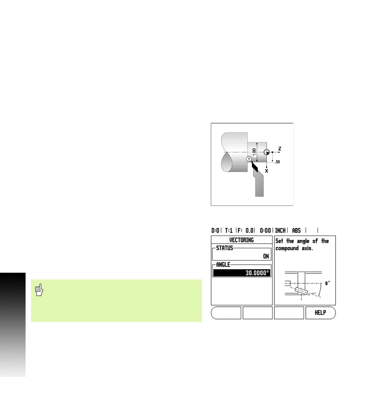
Vectoring
Vectoring breaks down the movement of the compound axis into the
crossfeed or longitudinal axes See Fig. I.36. If you are turning threads,
for example, vectoring lets you see the diameter of the thread in the
X-axis display, even though you are moving the cutting tool with the
compound axis handwheel. With vectoring enabled, you can preset
the desired radius or diameter in the X-axis, so that you can “machine
to zero”.
Press the VECTORING hard key.
Press the ON soft key to enable the vectoring feature.
Arrow down to the Angle field to enter the angle between the
longitudinal slide and top slide with 0° indicating the top slide is
moving parallel to the longitudinal slide. Press ENTER.
Fig. I.35 Workpiece for radius/diameter display
Fig. I.36 Vectoring
When vectoring is used, the top slide (compound) axis
encoder must be assigned to the bottom display axis. The
crossfeed component of movement of the axis will then
be shown in the top display axis. The longitudinal
component of movement of the axis will be shown in the
middle display axis.