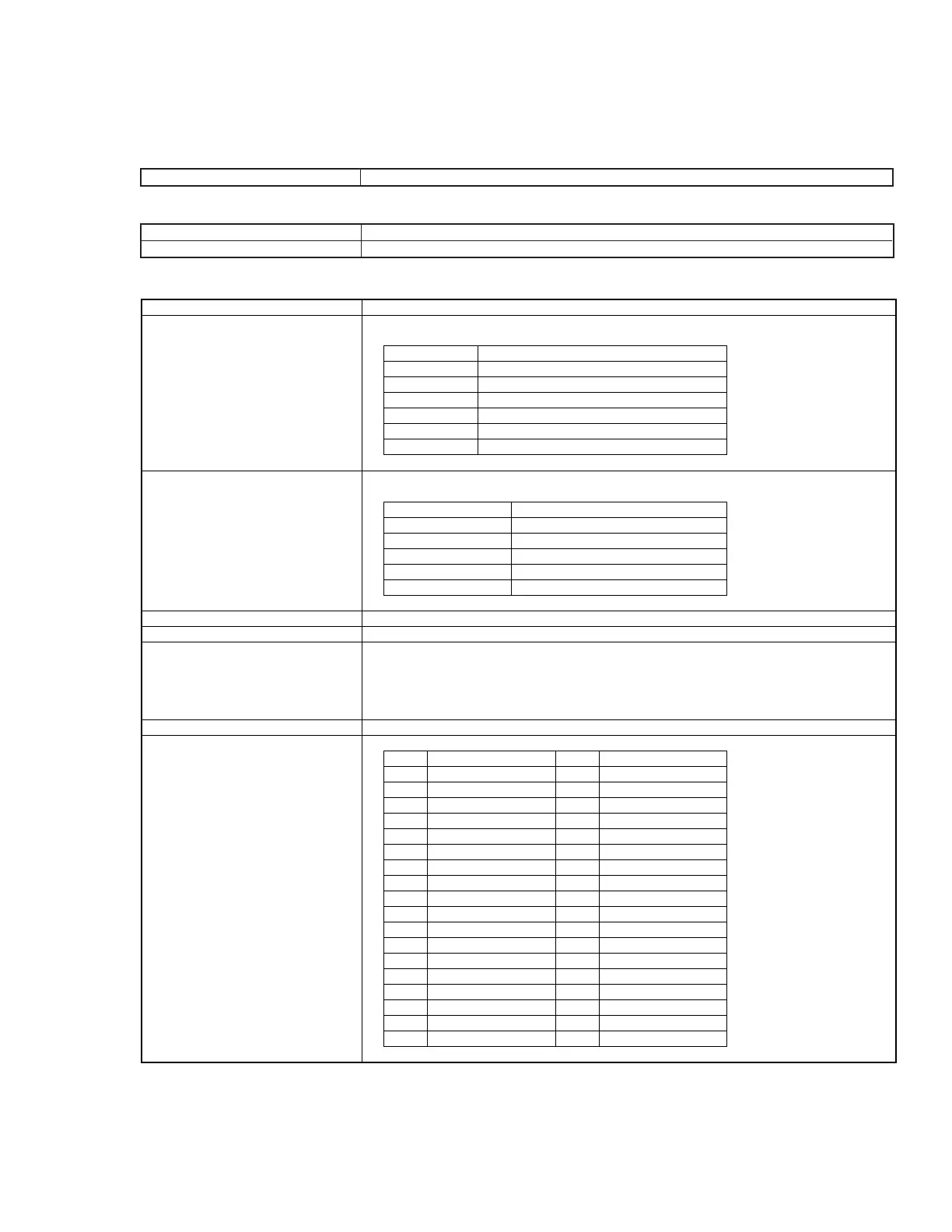
Function
System variables
PTL statements
Write strobe signal
DC output
Signal logical level
Cable connector
Connector pin layout
Controlling external equipment from PTA
The following controls are possible using PTA system variables:
Using PTA PTL statements allows control of interrupts input externally to the I/O ports
Outputs a write strobe pulse (negative pulse) to an external unit when output port C or D is controlled
Supplies +5 V ±0.5 V (max. 100 mA) power for external equipment use
Negative logic, TTL level
Rated current:
Output ports A, B:Max.output current Hi: 2.6 mA, Lo: 24 mA
Output ports C, D:Max.output current Hi: 15 mA, Lo: 24 mA
Other control output lines :Max. output current Hi: 0.4 mA, Lo: 8 mA
Amphenol 36 pins
System variable
IOA
IOB
IOC
IOD
EIO
EXO
Control description
Control of 8 bits parallel output port A
Control of 8 bits parallel output port B
Control of 8 bits parallel I/O port C
Control of 8 bits parallel I/O port D
Control of I/O switching port C and D
Control of trigger (I/O)
PTL statement
IOEN statement
IODI statement
IOMA statement
ON TO GOTO statement
ON TO GOSUB
Control description
Allow interrupt input
Prohibit interrupt input
Masks interrupt input
Changes program flow when interrupt occurs
Changes program flow when interrupt occurs
Pin No.
1
2
3
4
5
6
7
8
9
10
11
12
13
14
15
16
17
18
Name
GND
Trigger input
Trigger output1
Trigger output2
Output port A (0) LSB
Output port A (1)
Output port A (2)
Output port A (3)
Output port A (4)
Output port A (5)
Output port A (6)
Output port A (7) MSB
Output port B (0) LSB
Output port B (1)
Output port B (2)
Output port B (3)
Output port B (4)
Output port B (5)
Pin No.
19
20
21
22
23
24
25
26
27
28
29
30
31
32
33
34
35
36
Name
Output port B (6)
Output port B (7) MSB
I/O port C (0) LSB
I/O port C (1)
I/O port C (2)
I/O port C (3) MSB
I/O port D (0) LSB
I/O port D (1)
I/O port D (2)
I/O port D (3) MSB
Port C status 0/1:I/O
Port D status 0/1:I/O
Write strobe signal
Interrupt signal
(not used)
+5 V power supply
(not used)
(not used)
* Not installed with Option10: Centronics interface