4-4 Option 29, Power Meter Level Accuracy Option Verification
4-6 PN: 10580-00253 Rev. J S3xxE MM
Procedure Component Characterization:
1. Connect both MA2442D power sensors to the power meter and calibrate the sensors.
2. Connect the model 1870A power splitter to the MG3692A/B output and sensor B to one of the power
splitter outputs as shown on the previous page. (Figure 4-1 on page 4-5).
3. Install the 10 dB Fixed Attenuator to the other power splitter output and then connect sensor A to the
end of the Attenuator.
4. Set the power meter to display both Channels A and B. Press the Sensor key, the Cal Factor soft key, and
then the Freq soft key. Use the keypad to enter the value matching the frequency of MG3692A/B as the
input signal frequency, which sets the power meter to the proper power sensor cal factor. Repeat for
Channel B. Press the System key to display the power reading.
5. Adjust the power level of the MG3692A/B to get a reading on sensor A that matches the power level
(within ± 0.1 dB) in the first column of Table A-18, “Option 29, Characterization Chart for Power Meter
Verification” on page A-14.
6. Record the sensor B reading in the Required Sensor B Reading column of Table A-18.
7. Repeat Step 5 and Step 6 for the other power level in the first column of Table A-18, recording the
Sensor B reading in the second column.
8. Repeat the above steps for the next input frequency.
Power Meter Measurement Accuracy Procedure
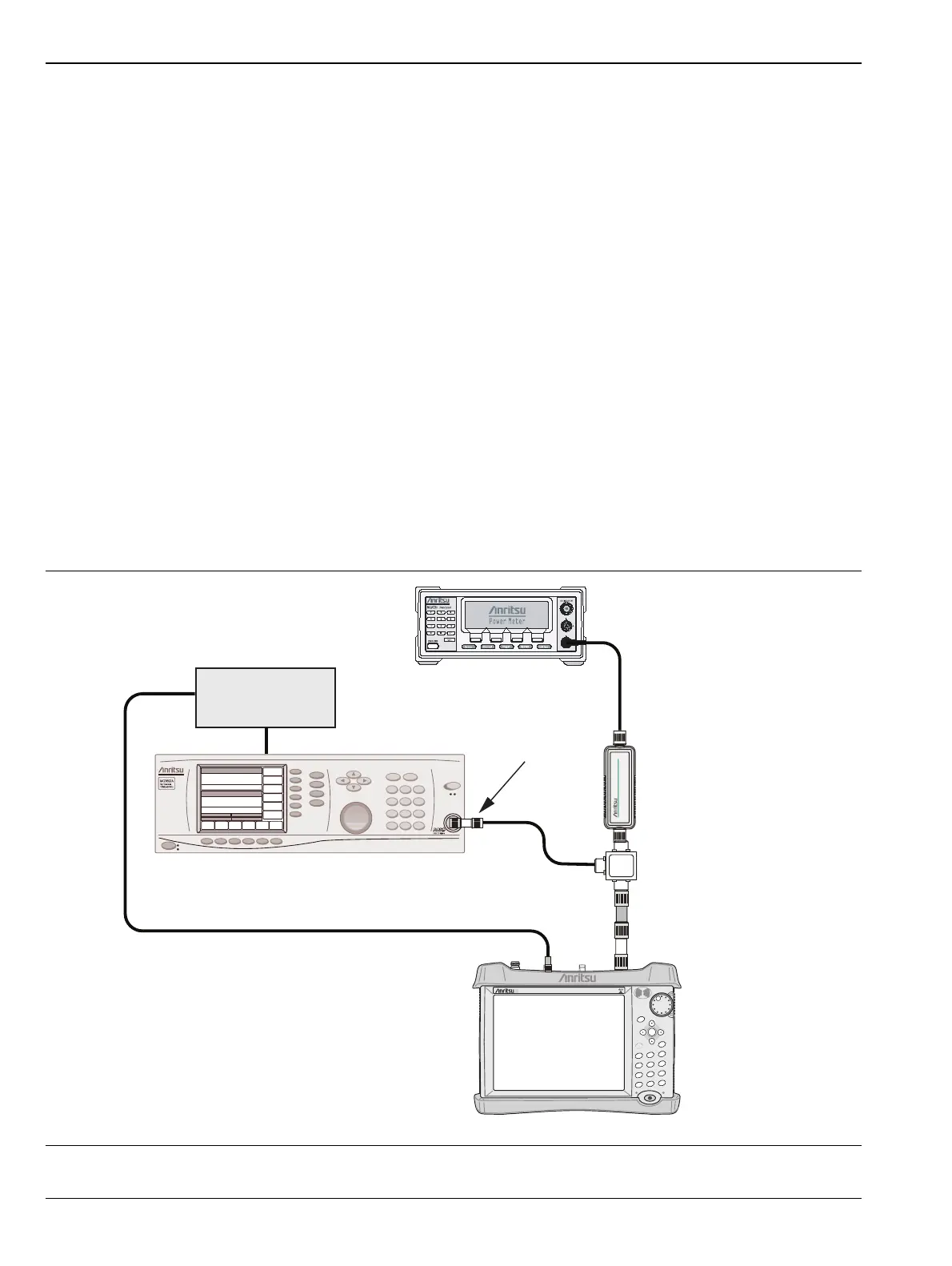
1. Connect the equipment as shown in Figure 4-2.
Figure 4-2. Power Meter Measurement Accuracy
S3xxE Site Master
Power Charge
+/-
.
0
3
Sweep
2
Calibrate
1
Preset
6
Limit
5
Trace
4
Measure
9
Mode
8
System
7
File
Shift
Back
Enter
ESC
SiteMaster
S332E
MG3692x Synthesized Signal Generator
10 MHz
Reference
ML2438A Power Meter
MA2442D
Sensor B
1870A
Power Splitter
Adapter
N(m) to N(m) Adaptor
10 dB Attenuator
 Loading...