- 14 -
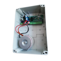
RSK24-2000/2500
CONTROL UNIT
English
INTRODUCTION
ABBREVIATIONS AND SYMBOLS USED IN THIS MANUAL
• Chap. = Chapter • p. = page • min. = minimum • Fig. = Figure
• Sect. = Section • Tab. = Table • max. = maximum
Warning
!
This symbol is used to mark information, instructions and procedures which if ignored
could lead to death and serious injury and which could create a long-term health and
environmental hazard.
Caution
This symbol is used to mark information, instructions and procedures which if ignored
can cause serious damage to the machine or to the product.
Information
The symbol is used to mark important information which if ignored could void your
warranty.
4
5
6
2
3
1
7
Introduction and safety precautions....................................................................................14-15
Product description
1.1 Product description .........................................................................................................................15
1.2 Permitted uses and applications ....................................................................................................15
1.3 Technical data ...............................................................................................................................15
Electrical installation and connecting up ................................................................................ 16
2.1 Fitting electrical equipment .............................................................................................................16
2.2 Connecting up ................................................................................................................................16
2.3 Connecting up to the mains power supply .....................................................................................16
2.4 Layout diagram and connections ...................................................................................................17
System start-up
3.1 System start up: self-teach cycle ....................................................................................................18
3.1.1 Self-teach procedure ......................................................................................................................18
3.1.2 Person Present operation .............................................................................................................18
3.2 Programming remote controls .......................................................................................................19
3.2A For PL-ECO plug-in twin-channel receiver .....................................................................................19
3.2B For UNICO Memory System receiver ............................................................................................19
3.3 Functional tests and adjustments ...................................................................................................19
Advanced programming and RESET procedure
4.1 Programming parameters ...............................................................................................................20
4.2 RESET procedure ..........................................................................................................................21
Operating modes
5.1 Operating modes .......................................................................................................................21-22
Control system functions
6.1 Motor management .......................................................................................................................23
6.2 Control devices ...............................................................................................................................23
6.3 Programmed functions ...................................................................................................................23
6.4 Safety function ...............................................................................................................................24
6.5 Checking connections on the display ............................................................................................24
Maintenance
7.1 Notes for maintenance technicians ................................................................................................25
7.2 Scheduled maintenance .................................................................................................................25
 Loading...