- 17 -
RSK24-2000/2500
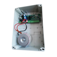
CONTROL UNIT
English
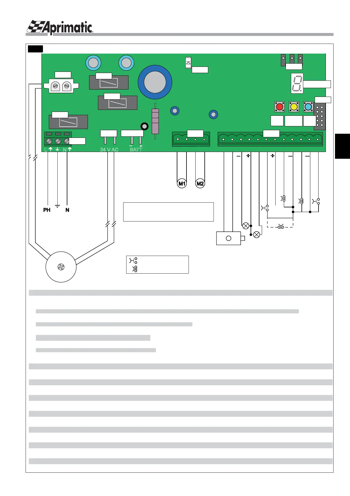
2.4 LAYOUT DIAGRAM AND CONNECTIONS
PHASE
EARTH
NEUTRAL
PHOTOCELL
FLASHING LIGHT
+24V ACCESSORIES
START
OPENING
SAFETY
STOP
GND
+ 24V
WARNING LIGHT 24V 3W max
PH N
230V 50Hz
+6% -10%
power supply
TRANSFORMER
SECONDARY 0-20VAC
PRIMARY 0-230VAC
M1 M2
MOTOR
1
MOTOR
2
12 Vac 15 W max.
ELECTRO-LOCK
ELECTRO-LOCK
GND
CAUTION!
When the NC contacts are not used, they must
be jumpered to the earth terminal (terminal 9 or 11). If you
do not do this the automation WILL NOT work.
NOTE
: The default setting for terminal 6 is NO (normally
open). It can be set to NC (normally closed) by setting
parameter H (sect. 7.1).
Brown
Blue
Brown
Blue
+
-
+
- -
START PEDESTRIAN
LEGEND:
M1
= motor 1st wing or single wing opening
M2
= motor 2nd wing opening
= NO type contact
= NC type contact
}
24 V AC BATT
-
+
L N
M1 M2 M3 M4 1 3 6 7 10 11 12245 89
J1J3
M5
J4
FS1
BATT
CN1
CN2
F1
F2
F3
Display
DL1
S1
Red
Fig.1
J1 terminal lock (12 pin):
1-2 Electric lock - 12 V AC output with maximum connectable load of 15W controlling the electric lock for approx. 1.5 seconds
in the opening stage.
3-4 Flashing LED, 24 V DC- two-wire cables with min. section 1 mm
2
. DO NOT use other types of f ashing light.
5-4 Warning light - 24 V DC output with maximum load of 3W for gate warning light.
6-9 Opening safety (NC safety contact) or pedestrian start (NO).
7-9 24 V power supply for accessories
8-9 Closing photocells input (NC safety contact)
10-9
STOP
(NC safety contact) to stop wing.
12-11
START
(NO) starts wing opening and closing.
J3 power terminal block with inputs for two 24 V DC motors - two-wire cable with min. section 1.5 mm
2
.
J4 connector for 230 V AC connection
M5 230 V AC phase-earth-neutral connection
FS1 24 V AC connection
CN1
3-pin Aprimatic connector for accessories
(
UNICO
receiver, access control decoder, etc.)
CN2 10-pin connector for PL-ECO receiver
BATT 24 V DC battery connection
F1 fuse for primary transformer protection
F2 fuse for external accessory protection (24 V DC)
F3 fuse for electronic circuit protection
DISPLAY (7 segments and one dot) to display parameters and parameter values
S1 RED button = Conf rm (used before self-teach to actuate motor 1 in the Person Present mode)
S2 YELLOW button = Exit (used also to display connections on display)
S3 BLUE button = Scroll the values available (used before self-teach to actuate motor 2 in the Person Present mode).
DL1 LED indicating that the board is powered up
S2
Yellow
S3
Blue
 Loading...