Relay Description P44x/EN HW/E33
MiCOM P441/P442 & P444
Page 33/44
R
P3028ENa
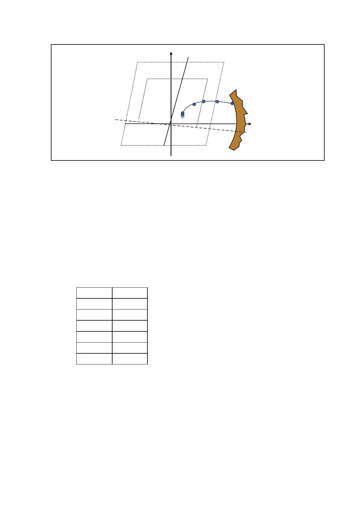
X
Z1
0
1
2
3
4..
FIGURE 13 - PHASE-TO-EARTH LOOP IMPEDANCE
4.5 Tripping Logic
Three tripping modes can be selected (in MiCOM S1: Distance Scheme\Trip Mode):
One-pole trip at T1 (if “1P. Z1 & CR” is set): Single-phase trip for fault in zone 1 at T1 and
Pilot Aided trip at T1. All other zones trip three-phase at their respective times for any fault
types (
∅-G, ∅-∅, ∅-∅-G, ∅-∅-∅, ∅-∅-∅-G).
One-pole trip at T1 and T2 (if “1P. Z1Z2 & CR” is set): Single-phase trip for Z1 at T1, Pilot
Aided trip at T1, and Z2 at T2. All other zones trip three-phase at their respective times for
any fault types (
∅-G, ∅-∅, ∅-∅-G, ∅-∅-∅, ∅-∅-∅-G). See section 2.8.2.5 chapter AP
(Tripping Mode).
Three- pole trip for all zones (Forces 3 poles): Three-phase trip for all zones at their
respective times for any fault types (
∅-G, ∅-∅, ∅-∅-G, ∅-∅-∅, ∅-∅-∅-G). Pilot aided
trips will be three-phase with times corresponding to the pilot logic applied.
Zone Time
Z1 T1
Z1X T1
Z2 T2
Zp Tp
Z3 T3
Z4 T4
There are five time delays associated with the six zones present. Zone 1 and extended zone
1 have the same time delay.
 Loading...