P44x/EN AD/E44 Update Documentation
Page 12/82
MiCOM P441, P442 & P444
P2086ENA
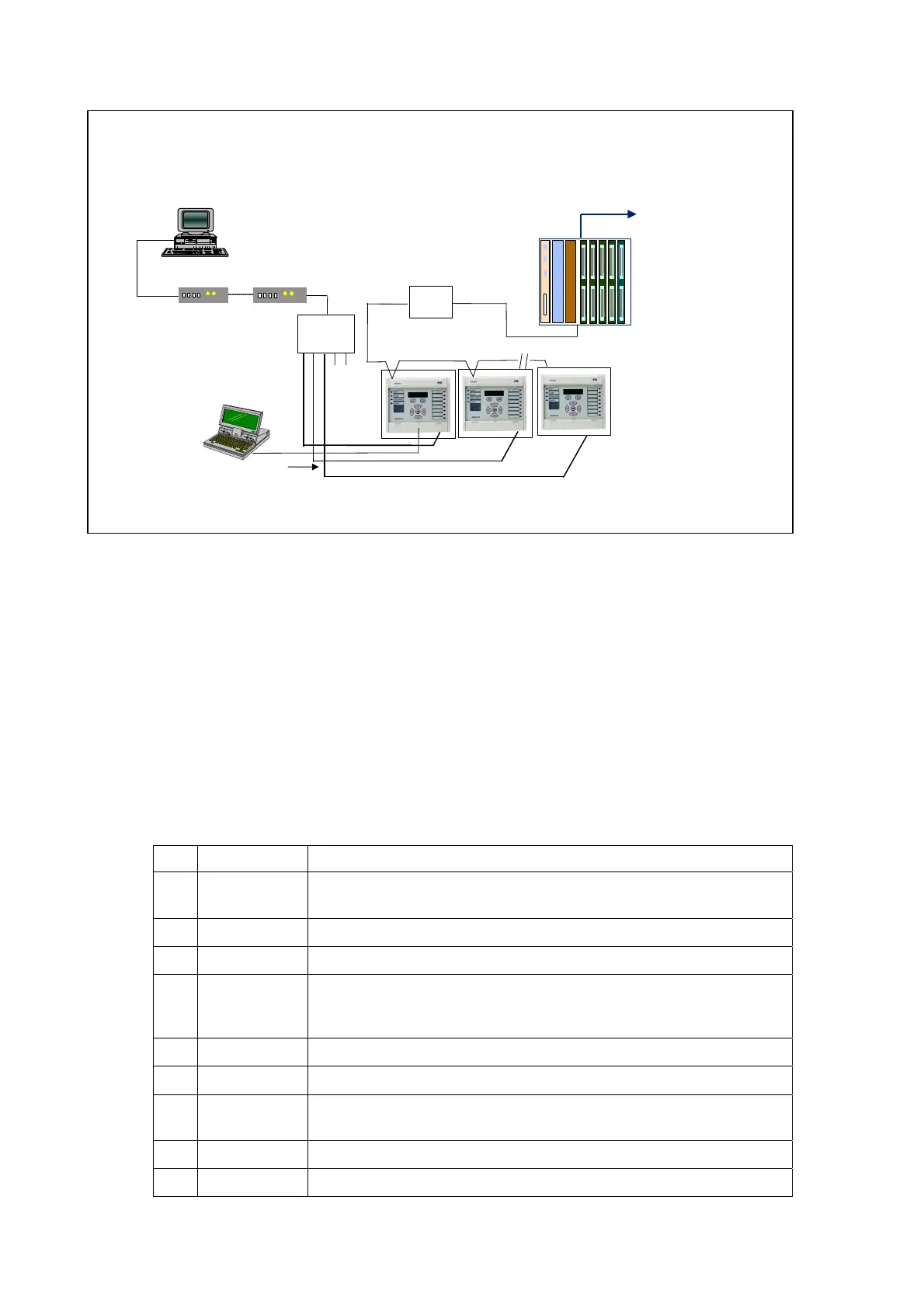
2 Master stations configuration: SCADA (Px40 1st RP) via CK222, EIA232 2nd rear
port via remote PC, max EIA232 bus distance 15m, PC local front/rear access
2
nd
RP (EIA232)
modem modem
EIA232
EIA232
EIA232
Master 1
Master 2
EIA232
POWER SUPPLY
CENTRAL PROCESSOR
R.T.U.
To SCADA
EIA232
splitter
Front port
MiCOMS1
EIA232
Note: 1
st
RP could be any chosen protocol, 2
nd
RP is always Courier
CK222
1
5
m
m
a
x
1
st
RP (Modbus / DNP/ IEC103)
EIA485
“EIA(RS)232 Application” example
SECOND REAR PORT EIA(RS)232 EXAMPLE
3.10 InterMiCOM Teleprotection
InterMiCOM is a protection signalling system that is an optional feature of MiCOM Px40
relays and provides a cost-effective alternative to discrete carrier equipment. InterMiCOM
sends eight signals between the two relays in the scheme, with each signal having a
selectable operation mode to provide an optimal combination of speed, security and
dependability in accordance with the application. Once the information is received, it may be
assigned in the Programmable Scheme Logic to any function as specified by the user’s
application.
3.10.1 Physical Connections
InterMiCOM on the Px40 relays is implemented using a 9-pin ‘D’ type female connector
(labelled SK5) located at the bottom of the 2
nd
Rear communication board. This connector
on the Px40 relay is wired in DTE (Data Terminating Equipment) mode, as indicated below:
Pin Acronym InterMiCOM Usage
1 DCD “Data Carrier Detect” is only used when connecting to modems
otherwise this should be tied high by connecting to terminal 4.
2 RxD “Receive Data”
3 TxD “Transmit Data”
4 DTR “Data Terminal Ready” is permanently tied high by the hardware
since InterMiCOM requires a permanently open communication
channel.
5 GND “Signal Ground”
6 Not used -
7 RTS “Ready To Send” is permanently tied high by the hardware since
InterMiCOM requires a permanently open communication channel.
8 Not used -
9 Not used -
Depending upon whether a direct or modem connection between the two relays in the
scheme is being used, the required pin connections are described below.