P44x/EN AD/E44 Update Documentation
Page 18/82
MiCOM P441, P442 & P444
2. HARDWARE MODULES
2.1 Processor board
The relay is based around a TMS320VC33-150MHz (peak speed) floating point, 32-bit digital
signal processor (DSP) operating at a clock frequency of 75MHz.,
2.2 Co-processor board
A second processor board is used in the relay for the processing of the distance protection
algorithms. The processor used on the second board is the same as that used on the main
processor board. The second processor board has provision for fast access (zero wait state)
SRAM for use with both program and data memory storage. This memory can be accessed
by the main processor board via the parallel bus, and this route is used at power-on to
download the software for the second processor from the flash memory on the main
processor board. Further communication between the two processor boards is achieved via
interrupts and the shared SRAM. The serial bus carrying the sample data is also connected
to the co-processor board, using the processor’s built-in serial port, as on the main processor
board.
(section removed)
From software version B1.0, coprocessor board works at 150Mhz.
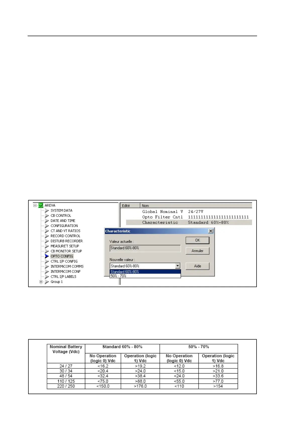
2.4.3 Universal opto isolated logic inputs
Each input also has selectable filtering which can be utilised (available since version C2.0).
Duals optos are available since C2.0 (hysteresis value selectable between 2 ranges)
The P440 series relays are fitted with universal opto isolated logic inputs that can be
programmed for the nominal battery voltage of the circuit of which they are a part i.e. thereby
allowing different voltages for different circuits e.g. signalling, tripping. From software version
C2.x they can also be programmed as Standard 60% - 80% or 50% - 70% to satisfy different
operating constraints.
Threshold levels are as follows:
 Loading...