P44x/EN AD/E44 Update Documentation
Page 70/82
MiCOM P441, P442 & P444
9.10.2.5
Physical Connections
InterMiCOM on the Px40 relays is implemented using a 9-pin ‘D’ type female connector
(labelled SK5) located at the bottom of the 2nd Rear communication board. This connector
on the Px40 relay is wired in DTE (Data Terminating Equipment) mode, as indicated below:
Pin Acronym InterMiCOM Usage
1 DCD “Data Carrier Detect” is only used when connecting to modems
otherwise this should be tied high by connecting to terminal 4.
2 RxD “Receive Data”
3 TxD “Transmit Data”
4 DTR “Data Terminal Ready” is permanently tied high by the hardware since
InterMiCOM requires a permanently open communication channel.
5 GND “Signal Ground”
6 Not used -
7 RTS “Ready To Send” is permanently tied high by the hardware since
InterMiCOM requires a permanently open communication channel.
8 Not used -
9 Not used -
TABLE 2 : INTERMiCOM D9 PORT PIN-OUT CONNECTIONS
Depending upon whether a direct or modem connection between the two relays in the
scheme is being used, the required pin connections are described below.
9.10.2.6
Direct Connection
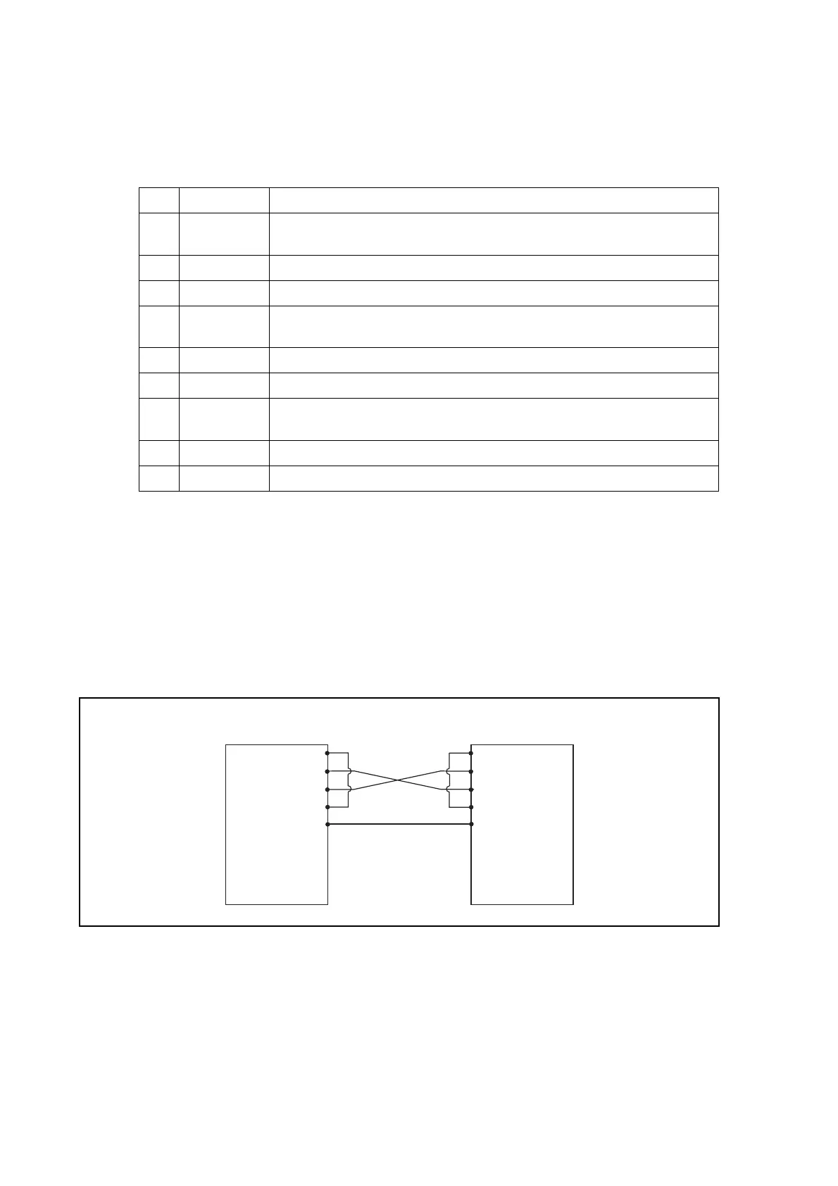
The EIA(RS)232 protocol only allows for short transmission distances due to the signalling
levels used and therefore the connection shown below is limited to less than 15m. However,
this may be extended by introducing suitable EIA(RS)232 to fiber optic convertors, such as
the AREVA T&D CILI203. Depending upon the type of convertor and fiber used, direct
communication over a few kilometres can easily be achieved.
Px40 Relay with
InterMiCOM
1
2
3
4
5
6
7
8
9
1
2
3
4
5
6
7
8
9
Px40 Relay with
InterMiCOM
DCD
RxD
TxD
DTR
GND
RTS
DCD
RxD
TxD
DTR
GND
RTS
-
-
-
-
-
-
-
-
-
-
-
-
P1150ENa
DIRECT CONNECTION WITHIN THE LOCAL SUBSTATION
This type of connection should also be used when connecting to multiplexers which have no
ability to control the DCD line.


 To Next Page