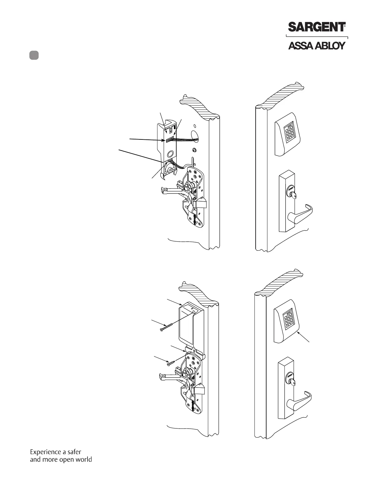
• Plug keypad connector into inside
escutcheon as shown.The back
plate can be removed to feed the
large connector through slot into
the circuit board to be assured of
proper fit. If connector is not fully
and properly seated on pins,
unit will not function properly.
• Plug smaller connector as shown
into inside escutcheon
NOTE: Both connectorsin-
stall only one way. Donot
offset the connectors.Be
sure connectors areseated
completely.
Small
connector
from ET
Control
Inside
of door
Back-
plate
Keypad
connector
Inside
Escutcheon
#8-32 x 1-1/2’’ Flat
head machine
screw
52-0086
Bracket
#8 x 1’’ Screw
Inside
of door
Keypad
Outside
of door
• Securely fasten top of
inside escutcheon to top
of keypad using a #8-32 x
1-1/2” machine screw
• Securely fasten bottom of
escutcheon (52-0086) to
door using #8 x 1” screw
Outside
of door
Rim Installation Instructions for
KP8800 Series (Continued)
Step #5 Inside Controller Assembly
7
Copyright © 2014. 2021, Sargent Manufacturing Company, an ASSA ABLOY Group company. All rights reserved.
Reproductions in whole or in part without express written permission of Sargent Manufacturing Company is prohibited.
02/28/21
12 A7137D • 800-810-WIRE (9473) • www.sargentlock.com
KP8877/KP8878 x ET x Lever Design
Keypad Operated RIM Exit Device
 Loading...