Cylinder
set screw
Figure 1
Correct Incorrect
Cylinder
Outside
of door
Latchbolt
Lever
Lever Arm
Chassis
Inside
of door
Exit chassis
Wire harness
(4) #10 Wood screws or
#10-24 machine screws
(4) #10 Wood
screws or #10-24
machine screws
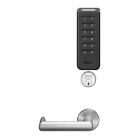
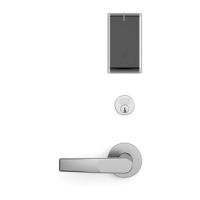
3. Cylinder Installation (KP8977 & 12-KP8977)
4. Securing Chassis to Door
• Position exit chassis on door so that lever arm
is under rear section of mortise lock lever. Then
lift up until latchbolt is completely retracted.
• Fasten exit chassis to door using (4) #10 wood
screws or #10-24 machine screws
Mortise Installation Instructions for
KP8900 Series (Continued)
• Insert cylinder into “ET” control.
Back out the cylinder set screw
in mortise lock.
• Thread cylinder clockwise into
mortise lock until the cylinder sits
flush and correct on “ET” control
(see Figure 1)
• Tighten cylinder set screw
8
Copyright © 2014. 2021, Sargent Manufacturing Company, an ASSA ABLOY Group company. All rights reserved.
Reproductions in whole or in part without express written permission of Sargent Manufacturing Company is prohibited.
02/28/21
15 A7137D • 800-810-WIRE (9473) • www.sargentlock.com
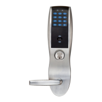
Installation Instructions
Mortise Exit Device
KP8977 / KP8978
 Loading...