Left Hand
Reverse Bevel
“LHRB”
Outside
Right Hand
Reverse Bevel
“RHRB”
NOTE: BEFORE STARTING
• Check hand of door - this device is not reversible
• Door should be fitted and hung
• Verify box label for size of exit device, function and hand
Step #1 Exit Hardware & Door Prep
Prep door according to installation instruction sheet A6705
Mortise Installation Instructions for
KP8900 Series
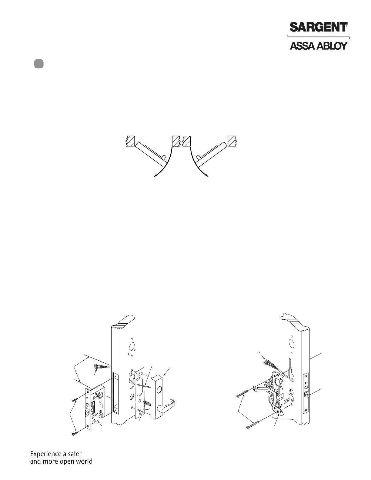
Step #2 Install Outside & Inside Trim
2. Inside Trim
• Route “ET” harness along track cutout for wood doors
and access hole for metal doors.
• Mount exit chassis carefully. Do not pinch
harness wires
• Secure chassis with (2) 1/4-20 x 2-3/8” flat head
machine screws
Centerline for
(2) 1/4 - 20 x 2-3/8’’
flat head
machine
screws
(2) Flat head
wood screws
Connector
Mortise lock
Wire
Harness
ET Control
ET Spindle
Outside
of door
Wire harness
Exit chassis
(2) 1/4 - 20 x 2 3/8’’
Flat head machine
screws
Inside
of door
1. Outside Trim
• For exterior applications “ET” gasket (52-0263)
should be used to seal between “ET” escutcheon
and outside door surface
• Route harness through under cut of cylinder hole
and out to other side of door
• Mount “ET” control onto door
8
Copyright © 2014. 2021, Sargent Manufacturing Company, an ASSA ABLOY Group company. All rights reserved.
Reproductions in whole or in part without express written permission of Sargent Manufacturing Company is prohibited.
02/28/21
14 A7137D • 800-810-WIRE (9473) • www.sargentlock.com
Installation Instructions
Mortise Exit Device
KP8977 / KP8978
 Loading...