8
3. Unpacking and Installation
(1) Unpacking
①Unpack the unit and visually check for any damages that may have occurred during transit.
②Make sure that the following components are included:
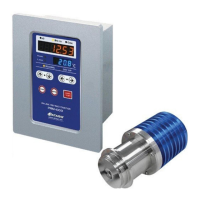
PRM-100α detection section ................................. 1
PRM-100α calculation display section .................. 1
Detection section - display section connecting cable
(hereinafter the DS-2 cable) .................................. 1
Recorder output cable (4-20mA) ........................... 1
3K clamp band 3S .................................................. 1
O-ring (Silicon) ....................................................... 1
O-ring (EPDM)........................................................ 1
Plain washer ........................................................... 4
Hexagon socket head bolt
(cross-recessed for assembling a spring washer) 2
Instruction manual (this manual) ........................... 1
Inspection certificate .............................................. 1
N These components are available with PRM-100αand built to standard specifications.
(2)Installation
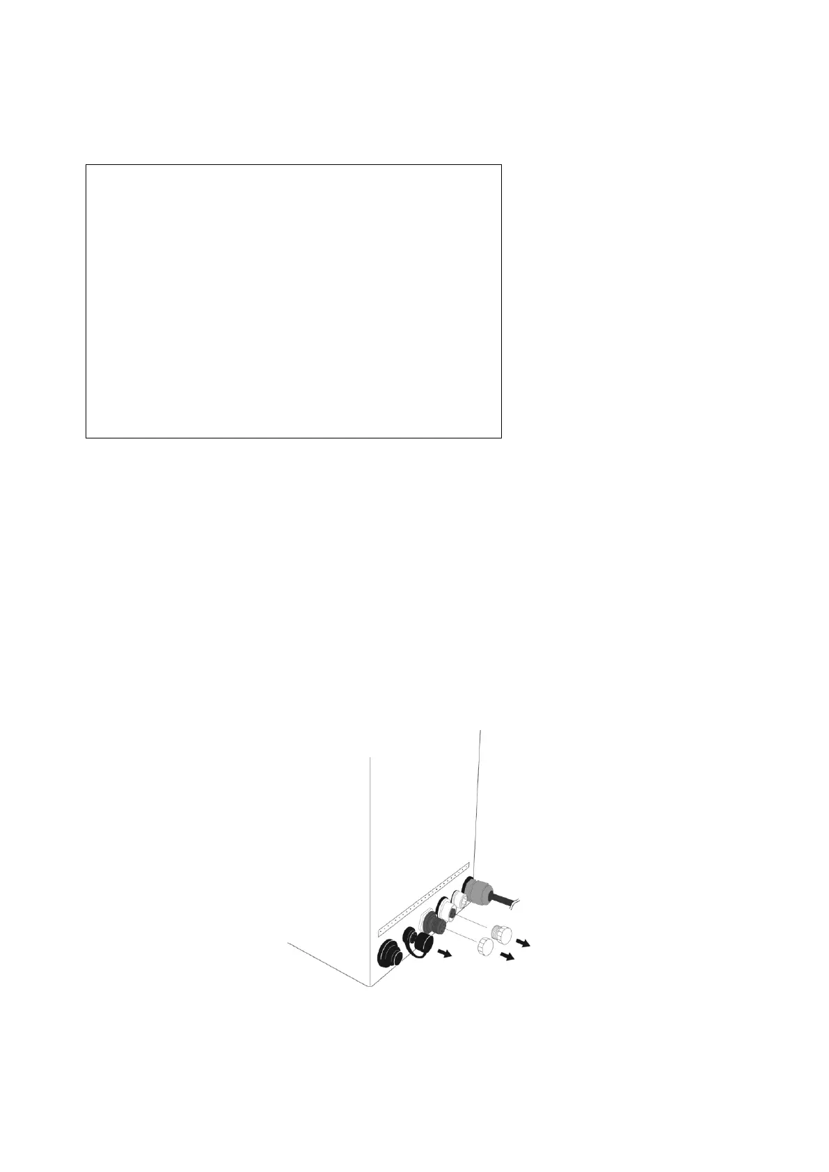
m Remove the socket caps from the display section (three caps) to access the terminals (Fig. 3-1).
①Run the unit from a power supply of 100V AC to 240V AC, 50/60Hz.
②Install the unit in an ambient temperature range of 5 to 40 ˚C.
③This unit contains precision components.
Avoid installing this unit in places that are exposed to direct sunlight or near a heat source, or where dust
or corrosive gases may accumulate.
④Install this unit in a location that is protected from strong vibration.
Exercise care during installation to avoid any impact or shock to the instrument, as such stress may affect
the performance of electronic components.
Fig. 3-1