21
(3) Alarm Output (high- and low-limiter output)
The alarm output functions based on the established range of acceptable measurement values.
When a value is detected that falls outside of the acceptable range alarm output is transmitted from the
detection section.
The high-limiter and low-limiter output circuit has a photocoupler with a transistor open collector in the final
stage. See the diagram on the following page before using the limiter circuit.
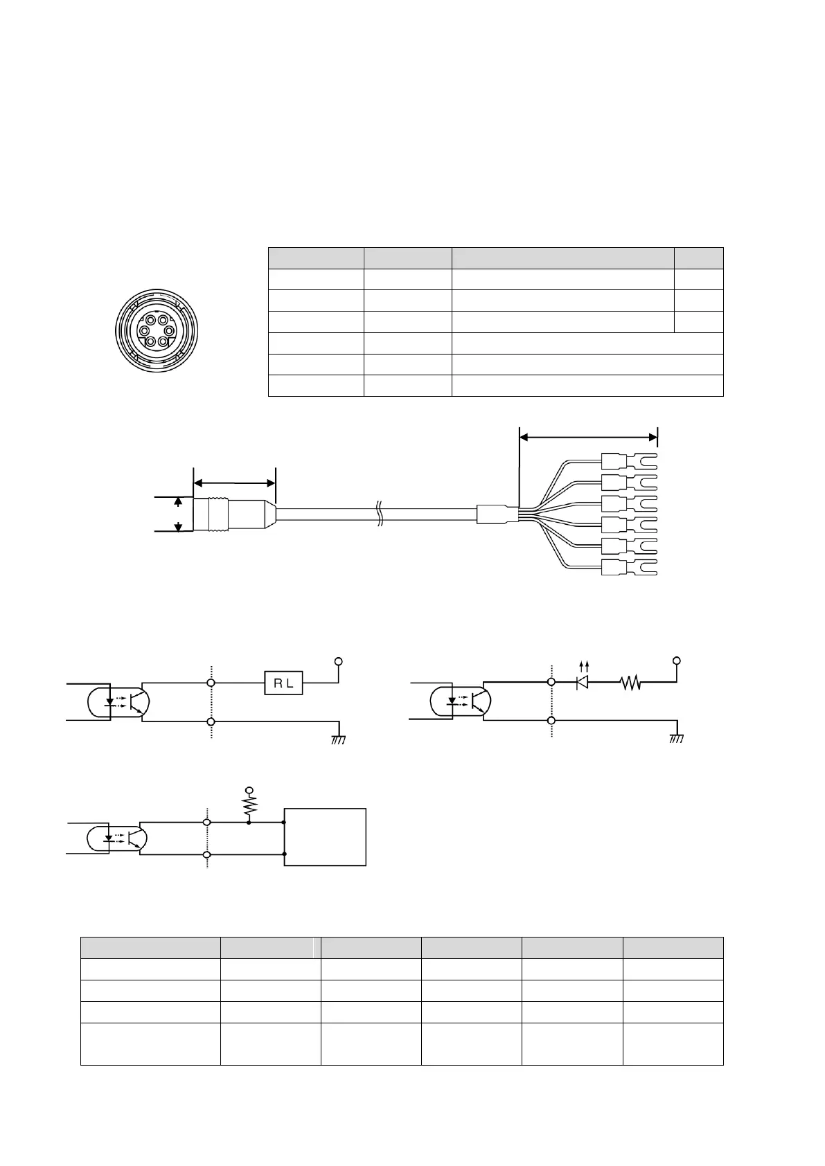
①Dedicated cable (option) specifications (Fig. 8-6 and Fig. 8-7)
Table 8-3 Lead wire color
This pin is not applicable to this unit.
This pin is not applicable to this unit.
This pin is not applicable to this unit.
Fig. 8-6
Fig. 8-7
②High- and low-limiter output typical applications
c. Feed a sequencer or the like at the signal level (TTL)
※R (resistance) and V+ are not necessary if the input to a sequencer or the like is pulled up.
Table 8-4 Recommended photocoupler operating conditions (Type TLP523-2)
Wire number plug front
view