3. Check that the electrical connections correspond to the applicable codes and that all wires are clamped
tight to their terminals.
The installation must be earthed and protected against short circuits by fuses of the inert type in all phases.
An isolating switch must be installed near the compressor.
4. Check transformer (T1) for correct connection.
Check the settings of drive motor overload relay (F21).
Check that the motor overload relay is set for manual resetting.
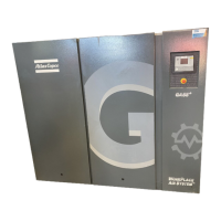
Example of electric cubicle on GA 55
+
up to GA 90
5. On air-cooled compressors, check the setting of circuit breaker (Q15). Also check that the switch on the
circuit breaker is in position I.
6. Fit air outlet valve (AV). See section Introduction for the location of the valve.
Close the valve.
Connect the air net to the valve.
Instruction book
2920 7109 60 161
 Loading...
