STbench EN Operation
© Atlas Copco Industrial Technique AB - 9839 0880 01
45
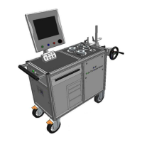
1. Disconnect from the relative connectors placed on the brake:
■
Signal cable.
■
Oil leakage tube.
■
Main oil tube.
If the elements listed above are not disconnected, they can be damaged irreparably
1 Signal cable 2 Oil leakage tube
3 Main oil tube
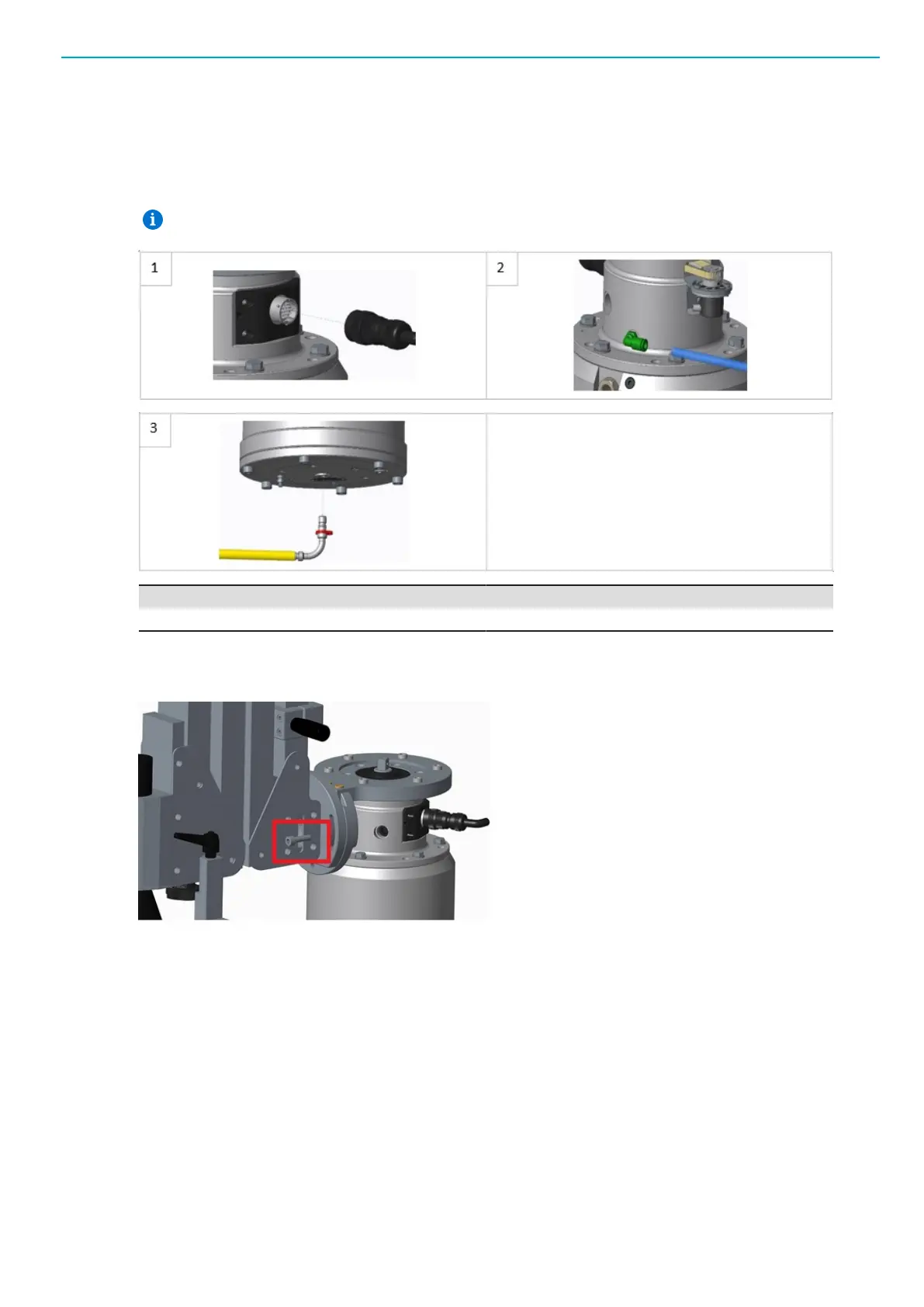
2. Remove the two screws (and the relative washers) placed on the tip-plate of the Articulated Arm that
lock the brake in a position perpendicular to the ground. In the following image, only one of the two
screws is shown. The two screws are symmetric respect to the arm.
3. Unscrew partially the nut that fix the tip-plate to the articulated arm (refer to the following figure).
4. Manually rotate the brake to the position to use during the test.
5. Screw the nut hat fix the tip-plate to the articulated arm.
6. Fix the brake using one or two screws and washer, according to the brake position.
7. Connect to the relative connectors placed on the brake (refer to the image above):
■
Main oil tube.
■
Oil leakage tube.
■
Signal cable.
8. Lock the Articulated Arm within the two mechanical blocks placed on each side of it: slide the me-
chanical blocks until they are in contact with the Articulated Arm and tighten the respective levers.
 Loading...