109
8126F–AVR–05/12
ATtiny13A
Note: a = address high bits, b = address low bits, H = 0 - Low byte, 1 - High Byte, o = data out, i = data in, x = don’t care
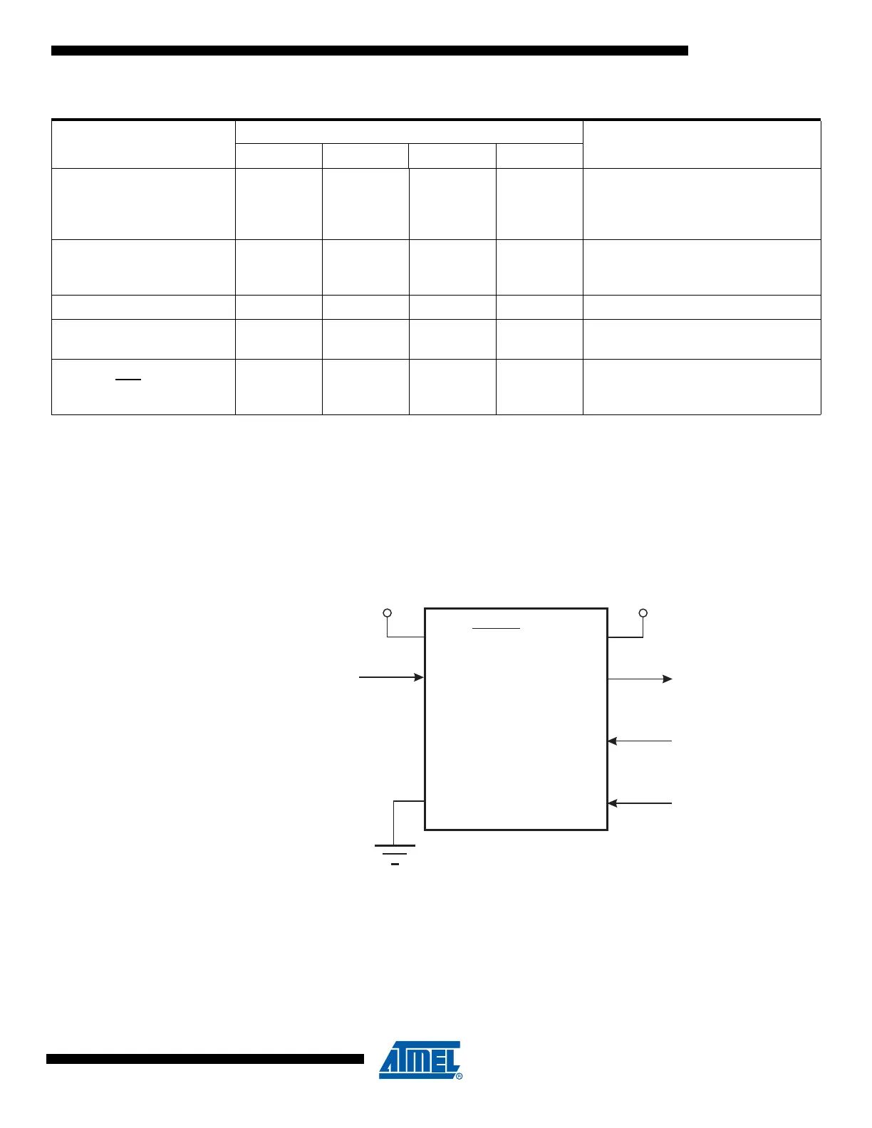
17.7 High-Voltage Serial Programming
This section describes how to program and verify Flash Program memory, EEPROM Data mem-
ory, lock bits and fuse bits in the ATtiny13A.
Figure 17-2. High-voltage Serial Programming
Read Fuse Byte
0101 H000 0000 H000 xxxx xxxx oooo oooo
Read fuse low/high byte. Bit “0” =
programmed, “1” = unprogrammed.
See “Fuse Bytes” on page 104 for
details.
Write Fuse Byte
1010 1100 1010 H000 xxxx xxxx iiii iiii
Set fuse low/high byte. Set bit to “0” to
program, “1” to unprogram. See “Fuse
Bytes” on page 104 for details.
Read Signature Byte
0011 0000 000x xxxx xxxx xxbb oooo oooo
Read Signature Byte o at address b.
Read Calibration Byte
0011 1000 000x xxxx 0000 000b oooo oooo
Read Calibration Byte. See
“Calibration Bytes” on page 105
Poll RDY/BSY
1111 0000 0000 0000 xxxx xxxx xxxx xxxo
If o = “1”, a programming operation is
still busy. Wait until this bit returns to
“0” before applying another command.
Table 17-9. Serial Programming Instruction Set (Continued)
Instruction
Instruction Format
OperationByte 1 Byte 2 Byte 3 Byte4
VCC
GND
SDO
SII
SDI
(RESET)
+1.8 - 5.5V
PB0
PB1
PB2
PB5
+11.5 - 12.5V
PB3
SCI