100
8126F–AVR–05/12
ATtiny13A
The LPM instruction uses the Z-pointer to store the address. Since this instruction addresses the
Flash byte-by-byte, also the LSB (bit Z0) of the Z-pointer is used.
16.5 EEPROM Write Prevents Writing to SPMCSR
Note that an EEPROM write operation will block all software programming to Flash. Reading the
fuses and lock bits from software will also be prevented during the EEPROM write operation. It is
recommended that the user checks the status bit (EEPE) in the EECR Register and verifies that
the bit is cleared before writing to the SPMCSR Register.
16.6 Reading Fuse and Lock Bits from Firmware
It is possible to read fuse and lock bits from software.
16.6.1 Reading Lock Bits from Firmware
Issuing an LPM instruction within three CPU cycles after RFLB and SELFPRGEN bits have
been set in SPMCSR will return lock bit values in the destination register. The RFLB and SELF-
PRGEN bits automatically clear upon completion of reading the lock bits, or if no LPM instruction
is executed within three CPU cycles, or if no SPM instruction is executed within four CPU cycles.
When RFLB and SELFPRGEN are cleared, LPM functions normally.
To read the lock bits, follow the below procedure.
1. Load the Z-pointer with 0x0001.
2. Set RFLB and SELFPRGEN bits in SPMCSR.
3. Issuing an LPM instruction within three clock cycles will return lock bits in the destina-
tion register.
If successful, the contents of the destination register are as follows.
See section “Program And Data Memory Lock Bits” on page 103 for more information on lock
bits.
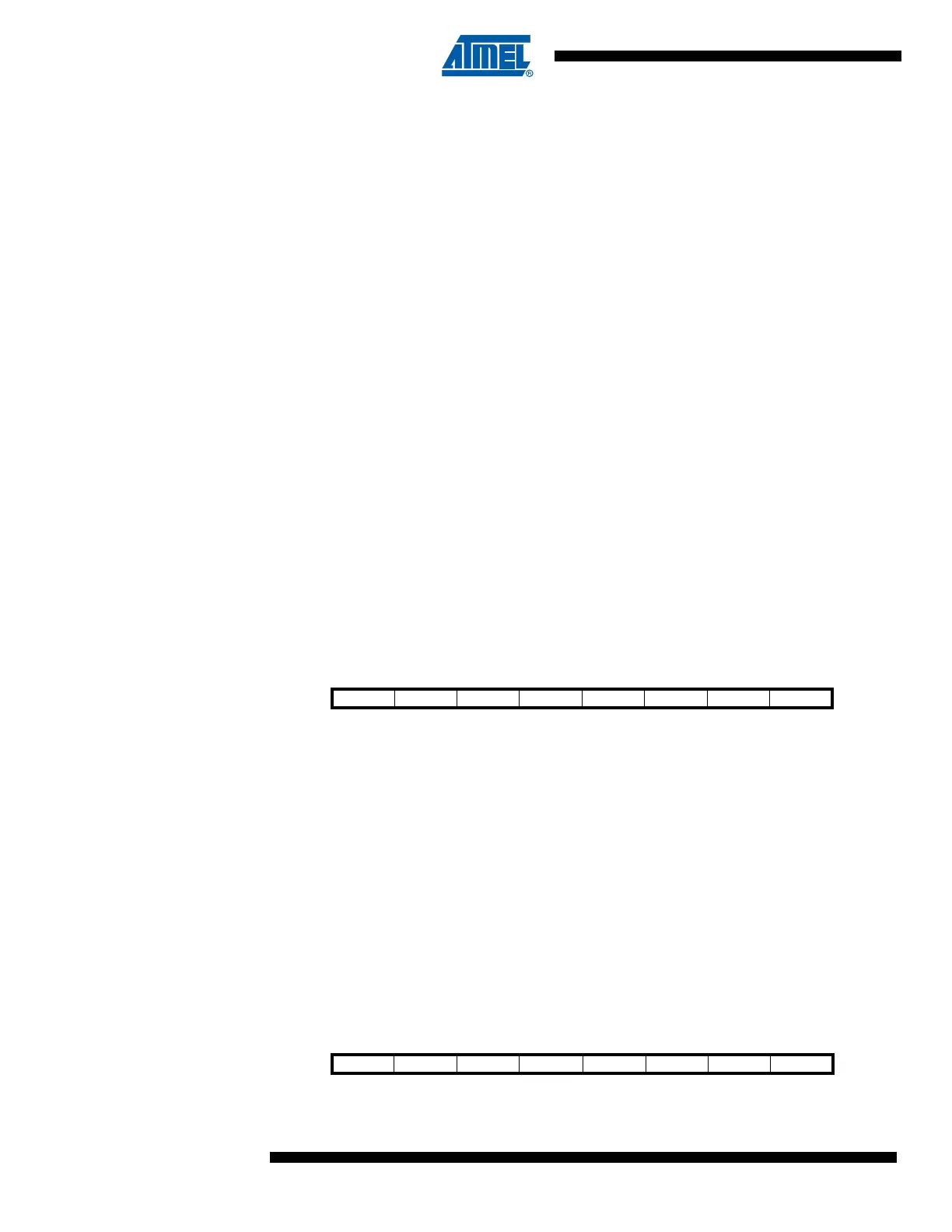
16.6.2 Reading Fuse Bits from Firmware
The algorithm for reading fuse bytes is similar to the one described above for reading lock bits,
only the addresses are different.
To read the Fuse Low Byte (FLB), follow the below procedure:
1. Load the Z-pointer with 0x0000.
2. Set RFLB and SELFPRGEN bits in SPMCSR.
3. Issuing an LPM instruction within three clock cycles will FLB in the destination register.
If successful, the contents of the destination register are as follows.
Bit 76543210
Rd ––––––LB2LB1
Bit 76543210
Rd FLB7 FLB6 FLB5 FLB4 FLB3 FLB2 FLB1 FLB0