36
8126F–AVR–05/12
ATtiny13A
8.2 Reset Sources
The ATtiny13A has four sources of reset:
• Power-on Reset. The MCU is reset when the supply voltage is below the Power-on Reset
threshold (V
POT
).
• External Reset. The MCU is reset when a low level is present on the RESET
pin for longer
than the minimum pulse length.
• Watchdog Reset. The MCU is reset when the Watchdog Timer period expires and the
Watchdog is enabled.
• Brown-out Reset. The MCU is reset when the supply voltage V
CC
is below the Brown-out
Reset threshold (V
BOT
) and the Brown-out Detector is enabled.
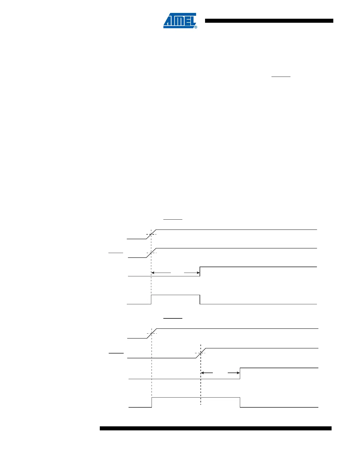
8.2.1 Power-on Reset
A Power-on Reset (POR) pulse is generated by an On-chip detection circuit. The detection level
is defined in “System and Reset Characteristics” on page 120. The POR is activated whenever
V
CC
is below the detection level. The POR circuit can be used to trigger the Start-up Reset, as
well as to detect a failure in supply voltage.
A Power-on Reset (POR) circuit ensures that the device is reset from Power-on. Reaching the
Power-on Reset threshold voltage invokes the delay counter, which determines how long the
device is kept in RESET after V
CC
rise. The RESET signal is activated again, without any delay,
when V
CC
decreases below the detection level.
Figure 8-2. MCU Start-up, RESET
Tied to V
CC
Figure 8-3. MCU Start-up, RESET Extended Externally
V
RESET
TIME-OUT
INTERNAL
RESET
t
TOUT
V
POT
V
RST
CC
RESET
TIME-OUT
INTERNAL
RESET
t
TOUT
V
POT
V
RST
V
CC