119
8126F–AVR–05/12
ATtiny13A
18.4 Clock Characteristics
18.4.1 Calibrated Internal RC Oscillator Accuracy
It is possible to manually calibrate the internal oscillator to be more accurate than default factory
calibration. Note that the oscillator frequency depends on temperature and voltage. Voltage and
temperature characteristics can be found in Figure 19-59 on page 154, Figure 19-60 on page
154, Figure 19-61 on page 155, Figure 19-62 on page 155, Figure 19-63 on page 156, and Fig-
ure 19-64 on page 156.
Notes: 1. Accuracy of oscillator frequency at calibration point (fixed temperature and fixed voltage).
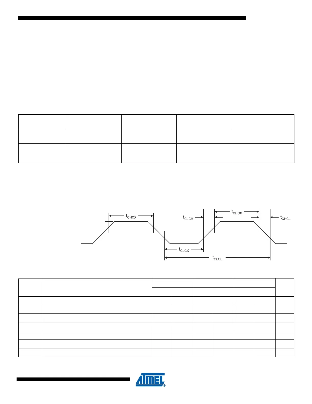
18.4.2 External Clock Drive
Figure 18-2. External Clock Drive Waveform
Table 18-2. Calibration Accuracy of Internal RC Oscillator
Calibration
Method Target Frequency V
CC
Temperature
Accuracy at given Voltage
& Temperature
(1)
Factory
Calibration
4.8 / 9.6 MHz 3V 25°C±10%
User
Calibration
Fixed frequency within:
4 – 5 MHz / 8 – 10 MHz
Fixed voltage within:
1.8 – 5.5V
Fixed temperature
within:
-40°C to +85°C
±2%
Table 18-3. External Clock Drive
Symbol Parameter
V
CC
= 1.8 - 5.5V V
CC
= 2.7 - 5.5V V
CC
= 4.5 - 5.5V
UnitsMin. Max. Min. Max. Min. Max.
1/t
CLCL
Clock Frequency 0 4 0 10 0 20 MHz
t
CLCL
Clock Period 250 100 50 ns
t
CHCX
High Time 100 40 20 ns
t
CLCX
Low Time 100 40 20 ns
t
CLCH
Rise Time 2.0 1.6 0.5 µs
t
CHCL
Fall Time 2.0 1.6 0.5 µs
Δt
CLCL
Change in period from one clock cycle to the next 2 2 2 %