120
8126F–AVR–05/12
ATtiny13A
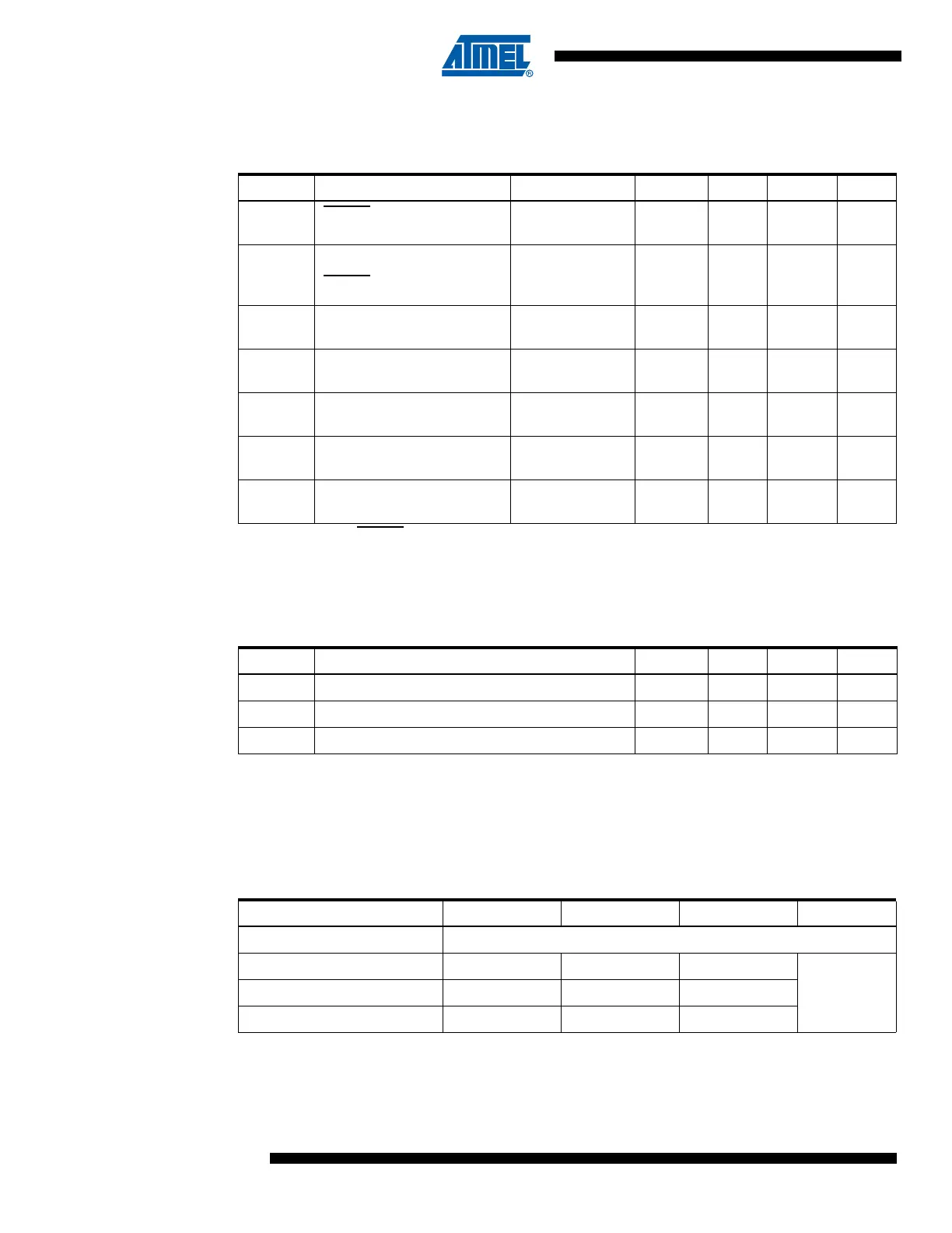
18.5 System and Reset Characteristics
Note: 1. When RESET pin used as reset (not as I/O).
2. Not tested in production.
18.5.1 Enhanced Power-On Reset
Note: 1. Values are guidelines only.
2. Threshold where device is released from reset when voltage is rising.
3. The Power-on Reset will not work unless the supply voltage has been below V
POA
.
18.5.2 Brown-Out Detection
Note: 1. V
BOT
may be below nominal minimum operating voltage for some devices. For devices where
this is the case, the device is tested down to V
CC
= V
BOT
during the production test. This guar-
antees that a Brown-out Reset will occur before V
CC
drops to a voltage where correct
operation of the microcontroller is no longer guaranteed.
Table 18-4. Reset, Brown-out, and Internal Voltage Characteristics
Symbol Parameter Condition Min Typ Max Units
V
RST
RESET Pin Threshold
Voltage
0.2 V
CC
0.9V
CC
V
t
RST
Minimum pulse width on
RESET
Pin
(1)
V
CC
= 1.8V
V
CC
= 3V
V
CC
= 5V
2000
700
400
2500
2500
2500
ns
V
HYST
Brown-out Detector
Hysteresis
(2)
50 mV
t
BOD
Min Pulse Width on
Brown-out Reset
(2)
2µs
V
BG
Internal bandgap reference
voltage
V
CC
= 5V
T
A
= 25°C
1.0 1.1 1.2 V
t
BG
Internal bandgap reference
start-up time
(2)
V
CC
= 5V
T
A
= 25°C
40 70 µs
I
BG
Internal bandgap reference
current consumption
(2)
V
CC
= 5V
T
A
= 25°C
15 µA
Table 18-5. Characteristics of Enhanced Power-On Reset. T
A
= -40 to +85°C
Symbol Parameter Min
(1)
Typ
(1)
Max
(1)
Units
V
POR
Release threshold of power-on reset
(2)
1.1 1.4 1.6 V
V
POA
Activation threshold of power-on reset
(3)
0.6 1.3 1.6 V
SR
ON
Power-On Slope Rate 0.01 V/ms
Table 18-6. V
BOT
vs. BODLEVEL Fuse Coding
BODLEVEL[1:0] Fuses Min
(1)
Typ
(1)
Max
(1)
Units
11 BOD Disabled
10 1.7 1.8 2.0
V01 2.5 2.7 2.9
00 4.1 4.3 4.5

 Loading...


