101
8126F–AVR–05/12
ATtiny13A
To read the Fuse High Byte (FHB), simply replace the address in the Z-pointer with 0x0003 and
repeat the procedure above.
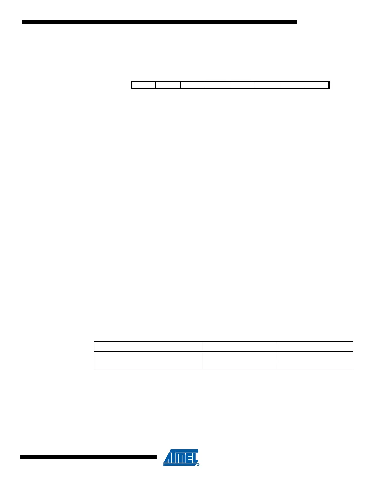
If successful, the contents of the destination register are as follows.
See sections “Program And Data Memory Lock Bits” on page 103 and “Fuse Bytes” on page 104
for more information on fuse and lock bits.
16.7 Preventing Flash Corruption
During periods of low V
CC
, the Flash program can be corrupted because the supply voltage is
too low for the CPU and the Flash to operate properly. These issues are the same as for board
level systems using the Flash, and the same design solutions should be applied.
A Flash program corruption can be caused by two situations when the voltage is too low. First, a
regular write sequence to the Flash requires a minimum voltage to operate correctly. Secondly,
the CPU itself can execute instructions incorrectly, if the supply voltage for executing instructions
is too low.
Flash corruption can easily be avoided by following these design recommendations (one is
sufficient):
1. Keep the AVR RESET active (low) during periods of insufficient power supply voltage.
This can be done by enabling the internal Brown-out Detector (BOD) if the operating
voltage matches the detection level. If not, an external low V
CC
reset protection circuit
can be used. If a reset occurs while a write operation is in progress, the write operation
will be completed provided that the power supply voltage is sufficient.
2. Keep the AVR core in Power-down sleep mode during periods of low V
CC
. This will pre-
vent the CPU from attempting to decode and execute instructions, effectively protecting
the SPMCSR Register and thus the Flash from unintentional writes.
16.8 Programming Time for Flash when Using SPM
The calibrated RC Oscillator is used to time Flash accesses. Table 16-1 on page 101 shows the
typical programming time for Flash accesses from the CPU.
Note: 1. The min and max programming times is per individual operation.
Bit 76543210
Rd FHB7 FHB6 FHB5 FHB4 FHB3 FHB2 FHB1 FHB0
Table 16-1. SPM Programming Time
(1)
Symbol Min Programming Time Max Programming Time
Flash write (Page Erase, Page Write, and
write lock bits by SPM)
3.7 ms 4.5 ms