EasyManua.ls Logo

Atmel ATtiny13A User Manual

Atmel ATtiny13A
176 pages
To Next Page IconTo Next Page
To Previous Page IconTo Previous Page
Page #11 background imageLoading...
Page #11 background image
11
8126F–AVR–05/12
ATtiny13A
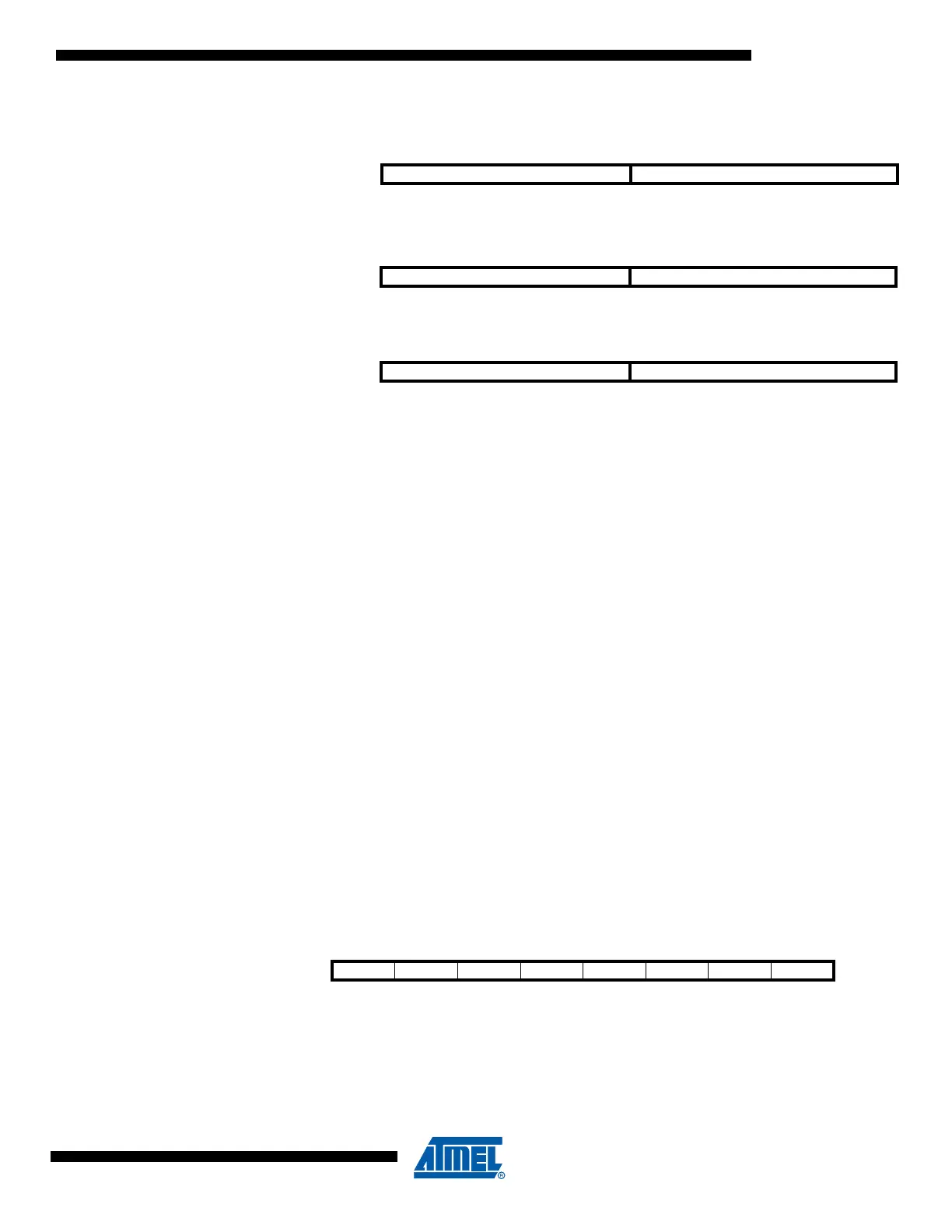
Figure 4-3. The X-, Y-, and Z-registers
In the different addressing modes these address registers have functions as fixed displacement,
automatic increment, and automatic decrement (see the instruction set reference for details).
4.5 Stack Pointer
The Stack is mainly used for storing temporary data, for storing local variables and for storing
return addresses after interrupts and subroutine calls. The Stack Pointer Register always points
to the top of the Stack. Note that the Stack is implemented as growing from higher memory loca-
tions to lower memory locations. This implies that a Stack PUSH command decreases the Stack
Pointer.
The Stack Pointer points to the data SRAM Stack area where the Subroutine and Interrupt
Stacks are located. This Stack space in the data SRAM is automaticall defined to the last
address in SRAM during power on reset. The Stack Pointer must be set to point above 0x60.
The Stack Pointer is decremented by one when data is pushed onto the Stack with the PUSH
instruction, and it is decremented by two when the return address is pushed onto the Stack with
subroutine call or interrupt. The Stack Pointer is incremented by one when data is popped from
the Stack with the POP instruction, and it is incremented by two when data is popped from the
Stack with return from subroutine RET or return from interrupt RETI.
The AVR Stack Pointer is implemented as two 8-bit registers in the I/O space. The number of
bits actually used is implementation dependent. Note that the data space in some implementa-
tions of the AVR architecture is so small that only SPL is needed. In this case, the SPH Register
will not be present.
4.5.1 SPL – Stack Pointer Low
15 XH XL 0
X-register 707 0
R27 (0x1B) R26 (0x1A)
15 YH YL 0
Y-register 707 0
R29 (0x1D) R28 (0x1C)
15 ZH ZL 0
Z-register 7070
R31 (0x1F) R30 (0x1E)
Bit 76543210
0x3D SP7 SP6 SP5 SP4 SP3 SP2 SP1 SP0 SPL
Read/Write R/W R/W R/W R/W R/W R/W R/W R/W
Initial Value10011111

Table of Contents

Question and Answer IconNeed help?

Do you have a question about the Atmel ATtiny13A and is the answer not in the manual?

Atmel ATtiny13A Specifications

General IconGeneral
BrandAtmel
ModelATtiny13A
CategoryMicrocontrollers
LanguageEnglish

Summary

Pin Configurations

ATtiny13A CPU Core

ALU and Status Register

Description of the Arithmetic Logic Unit (ALU) and the Status Register.

Reset and Interrupt Handling

How the microcontroller handles resets and interrupts for system control.

ATtiny13A Memories

Flash Program Memory

Details on the In-System Reprogrammable Flash Program Memory.

SRAM and EEPROM Data Memory

Description of SRAM and EEPROM data memory organization and features.

System Clock and Clock Options

Clock Sources and Prescaler

Details on available clock sources and the system clock prescaler.

Power Management and Sleep Modes

Sleep Modes Overview

Explanation of the different sleep modes available for power saving.

Software BOD Disable and Power Reduction

Methods for software control of Brown-out Detector and power reduction.

System Control and Reset

Resetting the AVR and Reset Sources

Details on resetting the AVR and the different reset sources.

Interrupts

Interrupt Vectors and External Interrupts

Details on interrupt vectors and external interrupt sources.

I/O Ports

I/O Ports Overview and General Digital I/O

Overview of I/O ports and their use as general digital inputs/outputs.

8-bit Timer/Counter0 with PWM

Timer/Counter Features and Overview

Features and overview of the 8-bit Timer/Counter0 module with PWM support.

Clock Sources, Counter Unit, and Output Compare Unit

Details on clock sources, counter unit, and output compare functionality.

Compare Match Output Unit, Modes of Operation, and Timing Diagrams

How compare matches affect output, operational modes, and timing.

Timer/Counter Prescaler

Analog Comparator

Analog Comparator Multiplexed Input and Register Description

Details on multiplexed inputs and register descriptions for the analog comparator.

Analog to Digital Converter (ADC)

ADC Operation and Conversion Start

Description of ADC operation and how to initiate a conversion.

debugWIRE On-chip Debug System

debugWIRE Features, Overview, and Interface

Features, overview, and physical interface of the debugwire system.

Self-Programming the Flash

Memory Programming

Electrical Characteristics

Absolute Maximum Ratings and DC Characteristics

Defines the absolute maximum operating conditions and DC electrical parameters.

Register Summary

Instruction Set Summary

Related product manuals