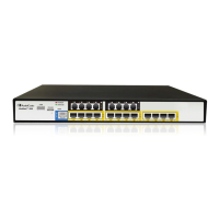
MSBR Series 5 MSBR Series
Hardware Installation Manual Contents
List of Figures
Figure 3-1: Mediant 800B MSBR Front Panel ....................................................................................... 15
Figure 3-2: Mediant 800C MSBR Front Panel ....................................................................................... 17
Figure 3-3: Mediant 800B MSBR Rear Panel ........................................................................................ 26
Figure 3-4: Mediant 800C MSBR Rear Panel ....................................................................................... 27
Figure 4-1: Location for Applying Rubber Feet ...................................................................................... 29
Figure 4-2: Mounting Brackets ............................................................................................................... 31
Figure 4-3: Attaching the Mounting Brackets ........................................................................................ 31
Figure 5-1: Earthing the Device ............................................................................................................. 34
Figure 5-2: Cabling WAN Copper GE Port – Mediant 800B MSBR ...................................................... 36
Figure 5-3: Cabling WAN Copper GE Port – Mediant 800C MSBR ...................................................... 36
Figure 5-4: Removing Protective Dust Plug – Mediant 800B MSBR ..................................................... 37
Figure 5-5: Removing Protective Dust Plug – Mediant 800C MSBR .................................................... 37
Figure 5-6: Cabling Fiber-Optic WAN GbE Port – Mediant 800B MSBR .............................................. 38
Figure 5-7: Cabling Fiber-Optic WAN GbE Port – Mediant 800C MSBR .............................................. 38
Figure 5-8: Cabling the SHDSL WAN Port ............................................................................................ 39
Figure 5-9: Cabling xDSL WAN Port – Mediant 800B MSBR ............................................................... 41
Figure 5-10: Cabling xDSL WAN Port – Mediant 800C MSBR ............................................................. 42
Figure 5-11: RJ-45 Connector Pinouts for E1/T1 WAN ......................................................................... 42
Figure 5-12: Example of Splitter Cable for Single E1/T1 WAN Port ...................................................... 43
Figure 5-13: Connecting E1/T1 WAN Port – Mediant 800B MSBR ....................................................... 43
Figure 5-14: Connecting T1 WAN Port – Mediant 800C MSBR ............................................................ 43
Figure 5-15: Plugging 3G/4G Cellular Modem into USB Port – Mediant 800B MSBR .......................... 44
Figure 5-16: Plugging 3G/4G Cellular Modem into USB Port – Mediant 800C MSBR ......................... 44
Figure 5-17: Connecting Cellular Antennas ........................................................................................... 46
Figure 5-18: Inserting SIM Card into SIM Slot ....................................................................................... 47
Figure 5-19: Cabling LAN Ports – Mediant 800B MSBR ....................................................................... 48
Figure 5-20: Cabling LAN Ports – Mediant 800C MSBR ....................................................................... 49
Figure 5-21: RJ-11 Connector Pinouts for FXS Interface ...................................................................... 49
Figure 5-22: Connecting FXS Interfaces – Mediant 800B MSBR ......................................................... 50
Figure 5-23: Connecting FXS Interfaces – Mediant 800C MSBR ......................................................... 50
Figure 5-24: RJ-11 Connector Pinouts for FXO Interface ..................................................................... 51
Figure 5-25: Connecting FXO Interfaces ............................................................................................... 51
Figure 5-26: RJ-11 Connector Pinouts for FXS Lifeline ........................................................................ 52
Figure 5-27: Cabling FXS Lifeline – Mediant 800B MSBR .................................................................... 52
Figure 5-28: Cabling FXS Lifeline – Mediant 800C MSBR .................................................................... 53
Figure 5-29: RJ-45 Connector Pinouts for BRI Ports ............................................................................ 53
Figure 5-30: Cabling BRI Ports – Mediant 800B MSBR ........................................................................ 54
Figure 5-31: Cabling BRI Ports – Mediant 800C MSBR ........................................................................ 54
Figure 5-32: Cabling BRI PSTN Fallback – Mediant 800B MSBR ........................................................ 55
Figure 5-33: Cabling BRI PSTN Fallback – Mediant 800C MSBR ........................................................ 56
Figure 5-34: RJ-48c Connector Pinouts for E1/T1 ................................................................................ 56
Figure 5-35: Cabling E1/T1 Ports – Mediant 800B MSBR .................................................................... 57
Figure 5-36: Cabling E1/T1 Ports – Mediant 800C MSBR .................................................................... 57
Figure 5-37: RS-232 Cable Adapter ...................................................................................................... 58
Figure 5-38: Cabling Serial Interface - Mediant 800B MSBR ................................................................ 59
Figure 5-39: Cabling Serial Interface - Mediant 800C MSBR ................................................................ 59
Figure 5-40: Connecting USB Storage Device – Mediant 800B MSBR ................................................ 60
Figure 5-41: Connecting USB Storage Device – Mediant 800C MSBR ................................................ 60
Figure 5-42: Cabling OSN Server Ports ................................................................................................ 62
Figure 5-43: Connecting to the Power Supply ....................................................................................... 64
Figure 5-44: Connecting DC Power Plug to DC Inlet ............................................................................ 65
Figure 5-45: Plugging AC Power Cord into AC/DC Adaptor ................................................................. 66
Figure 6-1: Opening the Fuse Cavity ..................................................................................................... 67
Figure 6-2: Removing the Power Fuse .................................................................................................. 67

 Loading...