MSBR Series 51 MSBR Series
Hardware Installation Manual 5. Cabling the Device
Cable specification:
Connector: RJ-11
Connector Pinouts:
Figure 5-24: RJ-11 Connector Pinouts for FXO Interface
Warnings:
• The device does not include primary telecom protection! When the FXO telephone
lines are routed outside the building, additional protection - usually a 350V three-
electrode Gas Discharge Tube (GDT) as described in ITU-T K.44 - must be provided
at the entry point of the telecom wires into the building (usually on the main
distribution frame / MDF), in conjunction with proper grounding. The center pin of the
GDT (MDF grounding bar) must be connected to the equipotential grounding bus bar
of the Telecommunication room.
• To protect against electrical shock and fire, use a minimum 26-AWG wire to connect
FXO ports to the PSTN.
• Ensure that the FXO ports are connected to the appropriate, external devices;
otherwise, damage to the device may occur.
• FXO ports are considered TNV-3.
To connect the FXO interfaces:
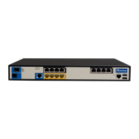
1. Connect one end of an RJ-11 cable to the FXO port (labeled FXO).
Figure 5-25: Connecting FXO Interfaces
2. Connect the other end of the cable to the required telephone interface: (e.g., telephone
exchange analog lines or PBX extensions).
 Loading...